Notebook PC User's Guide Model: W840DI First Edition: September 2008
User's Guide NOTICE Specifications and information found in this manual are subject to change without notice. Any changes therefore will be incorporated in future editions. The manufacturer assumes no responsibility for errors or omissions in this document. TRADEMARKS Windows™ is the trademark of Microsoft Corporation. Intel® is the trademark of Intel Corporation. Bluetooth® is the trademark owned by its proprietor. Other trademarks are properties of their respective owners.
User's Guide Standards The following standards are adopted throughout this manual: Notebook in boldface (with or without capitalization) refers to the notebook computer that you have purchased. Boldface type is also used to highlight important information in this document.
User's Guide This page is left blank intentionally.
User’s Guide Contents CONTENTS CHAPTER 1 BEFORE YOU BEGIN ................................................1-1 1.1 1.2 1.3 1.4 1.5 1.6 1.7 1.8 1.9 1.10 1.11 1.12 1.13 1.14 CHECKING WHAT YOU RECEIVED ................................................................. 1-1 EXAMINING YOUR COMPUTER ....................................................................... 1-2 THE POWER LED........................................................................................... 1-9 THE TWO SYSTEM LEDS ............
Contents User's Guide APPENDIX A - AGENCY REGULATORY NOTICES .................
User's Guide Before You Begin Chapter 1 Before You Begin Please read this section before you start using your computer. 1.1 Checking What You Received Your notebook package should contain the following items: (a) (b) (c) (d) (e) The Notebook. AC Adapter. AC Power Cord. CD Disc (Including Drivers, and User’s Guide). Battery Pack. (a) (b) Note: (c) (d) (e) You should keep the original factory carton and packing materials in case you need to ship the unit back for servicing.
Before You Begin 1.
User's Guide Note: Before You Begin The keyboard is with backlight design. When the system is powered on, you can press key combination (Fn+F10) to activate and deactivate the keyboard backlight function. For details on Function keys, please refer to Chapter 1.13. Note: Press this key combination (Fn+F4) to power on and power off the Web Cam module. After powering on the Web Cam, you need to activate its function through Windows™.
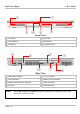
Before You Begin User's Guide Front View LCD Latch ODD LED Two Speakers Eject Button ODD Drive Emergency Hole Rear View RJ45 LAN Connector TV-In Connector VGA Connector USB/ e-SATA Connector Display Port Connector (Optional) HDMI Connector DC Jack USB Connector Note: Page 1-4 This USB/ e-SATA Connector supports connection to industry stand USB devices or e-SATA devices.
User's Guide Before You Begin Left View PCI Express Card Slot CMOS Reset Switch Media Card Slot (for SD/ MMC/ MS Cards) Two HDD Doors Ventilation Holes Page 1-5
Before You Begin User's Guide Right View SPDIF-Out Connector Volume Dial IEEE1394 Connector Ventilation Holes Microphone Jack USB Connectors Headphone Jack Kensington Lock Note: Page 1-6 Push the Volume Dial toward the headphone connector to increase audio volume. Push it in the opposite direction to decrease audio volume. To adjust the audio volume to your desired level, you need to repeatedly “push the dial to one direction and then let it go” until the desired audio volume is reached.
User's Guide Before You Begin Bottom View Compartment Door Woofer Ventilation Holes Battery Latch Two HDD Doors Battery Pack Warning: For better ventilation of heat generated and gathered inside the system unit, you are advised not to block the ventilation holes. For notebook with ventilation holes on the system chassis, please avoid putting system unit on fabric surfaces when it is powered on.
Before You Begin Note: User's Guide Some external USB devices consume more power than this system unit can provide. In this case, these USB devices have their own power cords. To make sure this kind of USB devices can function properly, please connect these devices to the AC source first before connecting to the system unit. Stereo Jack: Your headphone jack should have this type of connector as shown here. Mono Jack: Your microphone jack should have this type of connector as shown here.
User's Guide 1.3 Before You Begin The Power LED The Power LED is located on the power button (Chapter 1.6) and is used to indicate the power status of your system unit. The table below illustrates how the Power LED behaves in different situations. Off Blue Amber The system is off or in hibernation mode. Blinking The system is running on AC power and the battery is not inserted, or • The battery is fully charged. The system is in Sleep mode. Steady on The battery is charging.
Before You Begin 1.4 User's Guide The Two System LEDs The two System LEDs provide an alternate way to indicate power status of your system unit as also provided by the Power LED as described in Chapter 1.3. The table below illustrates how these two System LEDs behave in different situations. Off Blue The system is off or in hibernation mode. Steady on Blinking Off Amber The system is running on AC power and the battery is not inserted, or • The battery is fully charged. The system is in Sleep mode.
User's Guide 1.5 Before You Begin The Seven Status LEDs The Media Finger-Touch Button LED The LED would be lit (in a slightly different way though) in the below two conditions: • This LED would be indefinitely “on” when the seven media finger-touch buttons are disabled. This LED would be “off” when these buttons are reenabled again. • This LED would be momentarily “on” when the seven media finger-touch buttons are enabled and when any of these buttons are pressed/touched.
Before You Begin User's Guide The Num Lock LED The LED would be lit when the keyboard is in Num Lock mode. In this mode, the embedded numeric keypads can be used. Note: Page 1-12 The Seven Status LEDs are located near the topside of keyboard. For exact location, please refer to the Panoramic View diagram in Chapter 1.2.
User's Guide 1.6 Before You Begin The Power Button Power Button This Power Button is programmable by the user. For details on how to program this button, please refer to Power Options in the Control Panel of your Windows™ System. Note: The Power Button is located near the right side of the keyboard. For exact location, please refer to the Panoramic View diagram in Chapter 1.2.
Before You Begin 1.7 User's Guide The Two System Finger-Touch Buttons Internet Button Press this button to activate the internet function. Email Button Press this button to activate the email function. Note: The Two Finger-Touch Buttons are “finger-touch sensitive” and are located near the top of keyboard. For exact location, please refer to the Panoramic View diagram in Chapter 1.2.
User's Guide 1.8 Before You Begin The Seven Media Finger-Touch Buttons Play/Pause Button Press this button to play or pause media playback. Stop Button Press this button to stop media playback. Previous Track Button Press this button to skip to the previous track/chapter of media playback. Next Track Button Press this button to skip to the next track/chapter of media playback. Music Button Press this button to run the Music Program. DVD Button Press this button to run the DVD Program.
Before You Begin Note: User's Guide The system supports Windows™ MCE, and Windows™ Vista operating systems. Windows™ MCE supports full media center features. Both Windows™ Vista Home Premium and Windows™ Vista Ultimate include the full media center features as supported by Window™ MCE.
User's Guide 1.9 Before You Begin Attention On PCI Express And Media Card Slots Media Card slot door is now inserted into the system unit. Arrow on topside of Media Card slot door. Media slot door is now taken out from the system unit. PCI Express Card slot door is now inserted into the system unit. Arrow on topside of PCI Express Card slot door. PCI Express Card slot door is now taken out from the system unit.
Before You Begin • User's Guide When no card (SD/ MMC/ MS Cards) is inserted into the media slot, make sure this slot is covered by the “media slot door” as supplied together with this notebook. The purpose of this “media slot door” is to prevent foreign matters from entering into the system unit through this slot, when no card is inserted. When inserting this “media slot door”, please make sure the arrow is on the topside as shown above. Inserting this door upside down may cause damage to your notebook.
User's Guide Before You Begin 1.10 Operating Temperature Operating Temperature : 10ºC to 35ºC.
Before You Begin User's Guide 1.11 Resetting Your System Your system provides you an overclock option whereby you can choose to increase the overall system performance by overclocking the speed of the CPU processor. If you have chosen to overclock and are experiencing system’s instability, you can perform the steps below to reset your system: • Press the power button at least for four seconds to power off system.
User's Guide Warning: Before You Begin All devices and chipsets (that the system uses) operate relatively errorfree within their valid operating ranges. When you choose to overclock your system, you are allowing these devices and chipsets to operate outside their valid ranges; thus exposing your system to the potential risks of system’s instability, and/or shortening the lifespan of the system unit.
Before You Begin User's Guide 1.12 The Fingerprint Reader Finger Print Reader Rather than solely relying on traditional password to prevent from unauthorized access, this fingerprint reader offers your notebook an extra layer of protection. In order to take advantage on the functions and features of this fingerprint reader, you need to install the fingerprint reader program that comes along with the driver CD disc.
User's Guide Before You Begin 1.13 The Key The Function Key is located near the bottom-left corner of the keyboard. This key is used together with other keys to activate certain pre-defined functions. To activate these functions, press and hold down together with the keys described below: Sleep Switch Press this key combination (Fn+F1) to enter sleep mode. In sleep mode, the LCD display and selected devices would be switched off for less energy consumption.
Before You Begin User's Guide Mute/ Un-mute Switch Press this key combination (Fn+F6) to mute and to un-mute audio volume. Brightness Decreasing Press this key combination (Fn+F7) to decrease brightness of LCD display. Brightness Increasing Press this key combination (Fn+F8) to increase brightness of LCD display. Bluetooth Switch Press this key combination (Fn+F9) to power on and power off the Bluetooth® module.
User's Guide Note: Before You Begin The proper way to activate Wireless LAN, and Bluetooth® is as below: 1) Press this combination (Fn+F2) to power on Wireless LAN. 2) Press key combination (Fn+F9) to power on Bluetooth®. 3) Activate the application programs in Windows™. The effective range of the system Bluetooth® is 10 meters. Note: The keyboard backlight is dim and is not noticeable when the ambient brightness is high. The keyboard backlight consumes electrical power.
Before You Begin User's Guide 1.14 The AC Adapter Connect to system The adapter light Once the adapter is connected to a wall socket, the light on the adapter would be on immediately. In this case when the adapter is connected to the system unit, adapter starts providing power to the system unit as well as charging the batteries. 1.
User's Guide Battery Chapter 2 Battery 2.1 Battery Pack Your notebook is equipped with a high-energy rechargeable Lithium Ion (Li-Ion) battery pack. Battery life will vary depending on the product configuration, product model, applications loaded on the product, power management settings of the product, and the product features used by the customer. As with all batteries, the maximum capacity of this battery will decrease with time and usage. 2.
Battery 2.3 Q: A: User's Guide Questions and Answers: I can feel a mild heat next to the battery pack. Is it normal? The battery will generate heat during recharging and discharging. There is a protection circuit inside the notebook to prevent overheating. User needs not to worry. Q: A: My battery operation time is not as long as it should be. Why? Q: I did not use my spare battery for a few days. Even though it was fully recharged, there wasn't as much power left as a newly charged one.
User's Guide 2.4 Battery Battery Maintenance To maintain the battery pack's maximum capacity, you should occasionally let the notebook deplete its battery power completely before recharging. To carry out a complete depletion of the battery, disconnect the AC adapter and let your notebook consume the remaining battery power. To speed up the depletion, use the HDD as much as possible, and the LCD should be set as bright as possible.
Battery 2.6 User's Guide Reducing Power Consumption Although your notebook (together with the operating system) is capable of power conservation, there are measures you can take to reduce the power consumption: • Use the AC power whenever possible. • Lower the intensity of the LCD backlight. A very bright screen translates to higher power usage. • Try to use the HDD drive to read and write files, instead of using the external USB FDD. Note: 2.
User's Guide Memory Chapter 3 Memory Your notebook is equipped with a configurable memory unit. The industry standard JEDEC PC3-8500S (DDR3-1067) S.O.DIMM memory module sockets are available for memory upgrade to 4096MB. The table below illustrates some of the possible ways system memory can be configured.
Memory 3.1 User's Guide Limitation Of 32-bit Windows™ OS Below description applies to 32-bit Windows™ OS only, unless otherwise specified. 32-bit Windows™ OS is confined to the limitation of 4GB (232-1) of addressable memory space. This would not be an issue when you use Windows™ to view the system memory. That is when you have installed 4GB memory as listed above, Windows™ would report the system memory to be 4GB.
User's Guide 3.2 Memory Removing Memory Modules Below is the procedure on how to remove the memory modules. Two Memory Modules The location to pry up the compartment door • • • • • • • When installing back this door, make sure the door edge as hi-lit by the blue arrow is well aligned to the system unit; before you snap-in the rest of the door. Make sure the system is properly shutdown. Flip the system upside down as shown. Remove the battery pack as shown in Chapter 2.
Memory User's Guide • • • • • • To insert the memory modules, reverse the steps above. Page 3-4 Press the spring-locks sideways as shown by #1. The first memory module would pop up as shown by #2. Remove the first memory module. Press the spring-locks sideways as shown by #1. The second memory module would pop up as shown by #2. Remove the second memory module as shown by #3.
User's Guide The HDD Drives Chapter 4 The HDD Drives 4.1 The Two HDD Sockets The primary HDD socket The secondary HDD socket Your notebook is equipped with two sets of HDD socket. These sockets support industry standard 2.5”/9.5mm SATA-1 Gen1i (1.5Gb/s) and SATA-2 Gen2i (3.0Gb/s) hard disk drives.
The HDD Drives 4.2 User's Guide For RAID Users Your notebook supports RAID 0 and RAID 1 technology. In order to take advantage of this capability, you need to perform the below one-time procedure before installing Windows™ Vista™ operating system: • Install two SATA HDDs into the two HDD sockets. • Insert “Windows™ Vista™ SP1 OS” into the ODD drive. • Boot up system. Press F2 during boot up to enter BIOS Setup. • In BIOS Setup, set the SATA Mode Selection in Advanced menu to “RAID Enable”.
User's Guide 4.3 The HDD Drives For Non-RAID Users With the exception that you are going to install two Windows bootable HDD drives into these sockets, in general there is no need to distinguish which socket is primary socket and vice versa. Below are the three major scenarios: • One Windows bootable HDD drive: You are at your liberty to use either one of the two sockets. But primary socket is your preferred choice for the bootable HDD drive.
The HDD Drives 4.4 User's Guide Removing The Hard Disk Drives Below is the procedure on how to remove the hard disk drives. • • • • • • • HDD Drive To insert the HDD drive, reverse the steps above. Page 4-4 Make sure the system is properly shutdown. Flip the system upside down as shown. Remove the battery pack as shown in Chapter 2. Remove the two screws as shown by #1. Remove the two HDD drives as shown by #2. Remove the four screws as shown by #1.
User’s Guide Appendix A Appendix A - Agency Regulatory Notices A.1 Safety Instructions CAUTION: Please read these safety instructions carefully. CAUTION: Please keep this User's Manual for future reference. CAUTION: Please disconnect this equipment from AC outlet before cleaning. DO NOT use liquid or sprayed detergent for cleaning. Use a clean moistened cloth. CAUTION: The wall socket used should be positioned near the equipment and should be easily accessible.
Appendix A User's Guide CAUTION: Verify the voltage of the power source before connecting the unit to any power outlet. WARNING: DO NOT step on or place anything over the power cord. CAUTION: All cautions and warnings on the equipment should be noted. WARNING: If the equipment is not used for a long period of time, disconnect the equipment from the power source to avoid damage from power spikes. WARNING: NEVER pour any liquid into any openings; a fire or electrical shock is possible.
User’s Guide Appendix A CAUTION: DO NOT LEAVE THE EQUIPMENT IN TEMPERATURES BELOW -20ºC(-4ºF) OR ABOVE 60ºC(140ºF). IT MAY CAUSE DAMAGE TO THE EQUIPMENT. WARNING: This computer contains an internal lithium battery-powered real-time circuit. There is a risk of explosion and injury if the battery is incorrectly replaced or handled. Do not attempt to recharge, disassembled, immerse in water, or dispose of it in fire. Replacement should be done through your notebook dealer.
Appendix A User's Guide WARNING: Danger of explosion if battery is incorrectly replaced. Replace only with the same or equivalent type recommended by the manufacturer. Dispose of used batteries according to the manufacturer’s instructions. Explosionsgefahr bei unsachgemäßen Austausch der Batterie. Ersatz nur durch denselben oder einem vom Hersteller empfohlenem ähnlichen Typ. Entsorgung gebrauchter Batterien nach Angaben des Herstellers. WARNING: Your notebook contains a Ni-MH or Li-Ion battery pack.
User’s Guide Appendix A WARNING: Don't expose your notebook to excessive heat or coldness (frost). Don't drop, spill fluids or open the exterior of the case. This can damage the notebook and void the warranty. Caution: This notebook computer contains a certified optical module that is equivalent as a Class 1 LASER PRODUCT. Caution: According to ANSI/NFPA 70 of the National Electrical Code (NEC) Section 820.
Appendix A A.2 User's Guide Agency Notice Federal Communications Commission Notice This equipment has been tested and found to comply with the limits for a Class B digital device, pursuant to part 15 of the FCC Rules. These limits are designed to provide reasonable protection against harmful interference in a residential installation.
User’s Guide Appendix A FCC RF Radiation Exposure Statement • • • This transmitter must not be co-located or operating in conjunction with any other antenna or transmitter. This equipment complies FCC RF radiation exposure limits set forth for an uncontrolled environment. This equipment should be installed and operated with a minimum distance of 20 centimeters between the radiator and your body. If this device is going to be operated in 5.15 ~5.
Appendix A User's Guide Explosive Device Proximity Warning Warning: Do not operate a portable transmitter (such as a wireless network device) near unshielded blasting caps or in an explosive environment unless the device has been modified to be qualified for such use. Use On Aircraft Caution Caution: Regulations of the FCC and FAA prohibit airborne operation of radio-frequency wireless devices because their signals could interfere with critical aircraft instruments.
User’s Guide European Union Appendix A Notice Product with the CE Marking comply with the EMC Directive (2004/108/EC) and the Low Voltage Directive (73/23/EEC) issued by the Commission of the European Community and if this product has telecommunication functionality, the R&TTE Directive (1999/5/EC).
Appendix A User's Guide The wireless LAN device can currently be used indoors only in the following departments of mainland France.
User’s Guide Appendix A DGT Statement U.S. Regulations Governing the Use of Modems This equipment complies with Part 68 of the FCC Rules. On this equipment is a label that contains, among other information, the FCC registration number and Ringer Equivalence Number (REN) for this equipment. You must, upon request, provide this information to your telephone company. If your telephone equipment harms the telephone network, the Telephone Company may discontinue your service temporarily.
Appendix A User's Guide Japanese Modem Notice U.K. Modem Compliance Information This modem is approved by the secretary of state at the Department of Trade and Industry for connection to a single exchange line of the public switched telephone network run by certain licensed public telecommunication operators or system connected there to (Direct exchange lines only, not shared service or 1-1 carrier systems).
User’s Guide Appendix A This modem is only approved for use of the following facilities: • Storage of telephone numbers for retrieval by a predator mined code. • Initial proceed indication detection. • Automatic calling / automatic answering. • Tone detection. • Loud-speaking facility. This modem is not approved for connection to U.K./private speech-band services. This modem does not support an automatic re-dial function.
Appendix A This page is left blank intentionally.