TECHNICAL USER'S MANUAL FOR: PC/104 Peripheral boards MSMVGA 65545 based VGA/LCD controller #260399-1 Nordstrasse 11/F, CH-4542 Luterbach Tel.
DIGITAL-LOGIC AG MSMVGA Manual V1.0 COPYRIGHT 1998-1999 BY DIGITAL-LOGIC AG No part of this document may be reproduced, transmitted, transcribed, stored in a retrieval system, in any form or by any means, electronic, mechanical, optical, manual, or otherwise, without the prior written permission of DIGITAL-LOGIC AG. The software described herein, together with this document, are furnished under a license agreement and may be used or copied only in accordance with the terms of that agreement.
DIGITAL-LOGIC AG MSMVGA Manual V1.0 Table of Contents 1 1.1 1.2 1.3 1.4 1.5 1.6 1.7 PREFACE ...............................................................................................................4 How to use this Manual ........................................................................................... 4 Trademarks............................................................................................................. 4 Disclaimer ......................................................
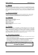
DIGITAL-LOGIC AG 1 MSMVGA Manual V1.0 PREFACE This manual is for integrators and programmers of systems based on the MICROSPACE card family. It contains information on hardware requirements, interconnections, and details of how to program the system. The specifications given in this manual were correct at the time of printing; advances mean that some may have changed in the meantime.
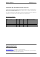
DIGITAL-LOGIC AG 1.5 Recycling Information Hardware: - Print: Software: 1.6 MSMVGA Manual V1.0 epoxy with glass fiber wires are of tin-plated copper - Components: ceramics and alloys of gold, silver check your local electronic recycling - no problems: re-use the diskette after formatting Technical Support 1. Contact your local Digital-Logic Technical Support in your country. 2. Use Internet Support Request form on http://www.digitallogic.ch -> support 3.
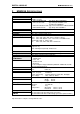
DIGITAL-LOGIC AG 2 MSMVGA Manual V1.0 MSMVGA SPECIFICATIONS Controller: Enhanced BIOS: Default Panels: Memory: 65545 from C&T VGA / LCD BIOS MultiBios Feature 1. CRT and MONO-LCD 2. CRT and TFT LCD Type Sharp Mono LM64P8XX Type Sharp TFT LQD011 and Toshiba TFT LTM9C015 3. CRT and STN-Color LCD Type Torisan STN Color LMCA53/22NAZ 4.
DIGITAL-LOGIC AG 3 MSMVGA Manual V1.0 VGA, LCD 3.
DIGITAL-LOGIC AG MSMVGA Manual V1.
DIGITAL-LOGIC AG MSMVGA Manual V1.
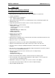
DIGITAL-LOGIC AG MSMVGA Manual V1.0 Simultaneous Display CRT: + Flatpanel type: Needed modifications: CRT CRT CRT CRT CRT + + + + + Mono Single Drive STN LCD Mono Dual Drive STN LCD Mono Single Drive TFT LCD Color Single Drive STN LCD Color Single Drive TFT LCD none none none none none 3.2 VGA/LCD BIOS Support Each LCD display needs a specific adapted VGA-BIOS. Standard this product is equiped with the CRT standard VGABIOS.
DIGITAL-LOGIC AG MSMVGA Manual V1.0 5 Description of the Connectors 5.1 VGA-Connector Analog Interface for Monitors Signal Name VGA-Connector Sub-D 15 pol VGA red VGA green VGA blue Horizontal Sync. Vertical Sync. Ground Bridge MICROSPACE Product MSMVGA/L Pin No. 1 2 3 13 14 7 8 + 11 Header Pin No.
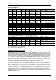
DIGITAL-LOGIC AG 5.2 J4 MSMVGA Manual V1.0 VGA Connector for Flatpanel Display LCD Connector VGA-LCD Interface (flatpanel signals): Signals P20-P23 are located on the J4M connector Pin Signal Pin Signal 1 3 5 7 9 11 13 15 17 19 21 23 25 27 29 M-Signal (altern.
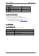
DIGITAL-LOGIC AG MSMVGA Manual V1.0 6 JUMPER LOCATION ON THE BOARD 6.1 The Jumpers on this MICROSPACE product 6.1.1 Flatpanel Interface Flatpanel Interface: J6 1-2 negative -35V Flatpanel Interface: VEE-Polarity 2-3 positive +35V 6.1.2 Standby the VGA Controller: Standby the VGA Controller: J9 (smd jumper) 1-2 Standby the VGA Controller: StnBY active (Default) 2-3 Standby 6.1.
DIGITAL-LOGIC AG MSMVGA Manual V1.0 6.1.5 Selection of the Flash Sector (for using C800-CFFF, as alternate Flash-BIOS Memory, use the 64k-GAL. The standard implementation is 32k-GAL!) J18, J19 Selected Sector: J18 J19 Sector 1 (Default) Sector 2 Sector 3 Sector 4 open closed open closed open open closed closed 6.1.6 VEE Generator supply If there is an external 12V power supply at the PC/104 BUS PIN B9, switch the Jumpers J25 and J26 to 2-3.
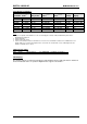
DIGITAL-LOGIC AG Jumper Locations R72 J27 J6 1 1 J26 1 J18 1 U14 J19 1 J25 J10 U13 J28 1 DIGITAL-LOGIC AG MSMVGA V1.0 JMP-LOCATION TOP-SIDE 0299 JM 1 J9 J29 1 1 J8 J14 J13 15 J4 - VGA/LCD CONNECTOR 6.2 MSMVGA Manual V1.
DIGITAL-LOGIC AG MSMVGA Manual V1.0 7 SPECIAL PERIPHERALS, CONFIGURATION, FUNCTIONS 7.1 Onboard BIAS Power generation (only on the MSMV104L) On the MSMV104L (low cost) board is no BIAS generator implemented. IMPORTANT: The onboard voltage generation must be adjusted and measured before the LCD panel is connected, otherwise the display may be destroyed. Follow these steps: 7.1.1 VEE Generation If there is an external 12V power supply at the PC/104 BUS PIN B9, switch the Jumpers J25 and J26 to 2-3.
DIGITAL-LOGIC AG MSMVGA Manual V1.0 7.1.3.
DIGITAL-LOGIC AG 8 POSSIBLE FAILURES 8.1 General LCD Failures MSMVGA Manual V1.0 Refer to the Flatpanel Manual by DIGITAL-LOGIC AG. 1. Check the LCD-BIOS. You have a special BIOS for every LCD. 2. Check the cable to the LCD. 3. Check the Jumper. 4. Check the power supply. 8.2 The LCD is not stable Try to place a resistor at the VEE to the GND. VEE MSMV LCD 10K-22K This occurs to LCDs which do not consume enough current. Try to raise the resistor values as much as possible.
DIGITAL-LOGIC AG 9 MSMVGA Manual V1.0 INDEX 1 N 16-Bit CPU Interface:........................................... 14 Negative voltage with 5V input ............................ 18 C P CRT Displays ......................................................... 9 Positive voltage with 5V input .............................. 17 F S Failures ................................................................ 19 Flash-BIOS Memory, ...........................................