
User`s manual


DIGITAL-LOGIC AG MSMVGA Manual V1.0
13
6JUMPER LOCATION ON THE BOARD
6.1 The Jumpers on this MICROSPACE product
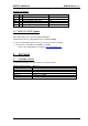
6.1.1 Flatpanel Interface
Flatpanel Interface: 1-2 2-3
J6 Flatpanel Interface:
VEE-Polarity
negative -35V positive +35V
6.1.2 Standby the VGA Controller:
Standby the VGA Controller: 1-2 2-3
J9 (smd jumper) Standby the VGA Controller: StnBY active
(Default)
Standby
6.1.3 Selection of the BIOS Address
Function:
Jumper Position, Address: Jumper Position, Address:
J10 Selection of the BIOS Address
FLASH Boot process: Flash
Operation
1-2 = C000 2-3 = C800
6.1.4 16-Bit CPU Interface:
16-Bit CPU Interface: Default-16 Bit:
J13 (smd jumper) SMEMR-MEMR closed = not used
open = 16Bit
J14 (smd jumper) SMEMW-MEMW closed = not used
open = 16Bit