User's Guide for Windows
Copyright 1999 by Microtek International, Inc. All rights reserved. Trademarks Microtek, ScanMaker, and ScanWizard 5 are trademarks of Microtek International, Inc. IBM PC is the trademark of International Business Machines Corporation. Windows and MS-DOS are trademarks of Microsoft Corporation. Other product or company names are trademarks or registered trademarks of their respective holders. Important Documents that you scan may be protected under copyright law.
Contents 1. Before You Begin 1-1 What is ScanWizard 5? .............................................................................................. 1-1 Standard & Advanced Control Panels ........................................................................ 1-2 Who Should Use the Standard Control Panel? ..................................................... 1-2 Who Should Use the Advanced Control Panel? ...................................................
Windows Basics ................................................................................................. 3-1 Basic Mouse and Keyboard Techniques ........................................................ 3-2 Choosing and Selecting Items ...................................................................... 3-2 Launching ScanWizard 5-Standard Tutorial ............................................................... 3-3 Launching from an Image Application .................................................
Resolution of Output Image ...................................................................................... 4-7 Intended Size of Output Image .................................................................................. 4-8 Improving Image Before Final Scan ............................................................................ 4-8 Output Image Setting Information ............................................................................. 4-9 Reset and Revert to Default Settings ..........
Option 2: Reducing the view ..................................................................... 5-21 Correcting images ................................................................................................... 5-22 Using the Advanced Image Correction dialog box .................................................... 5-23 Final Scan and Output Image Destinations .............................................................. 5-24 ScanWizard 5-Advanced Launched from an Application .....................
Monitor Gamma Setup .............................................................................. 6-24 Invert ........................................................................................................ 6-25 More command ......................................................................................... 6-26 The Help Menu ................................................................................................ 6-29 The Tool Buttons ..................................................
Using the Color Correction tool ................................................................. 6-68 Filters tool ....................................................................................................... 6-69 Blur filters ................................................................................................. 6-70 Sharpen filters ........................................................................................... 6-70 Edge Enhancement filter ..................................
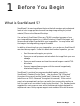
1 Before You Begin What is ScanWizard 5? ScanWizard 5 is scanning software that provides both amateur and professional levels of color image reproduction and scan stage image editing for printed material, 35mm color slides and filmstrips. You can launch ScanWizard 5 from any TWAIN-compliant program or from your image editing programs (e.g., Adobe Photoshop, Ulead PhotoImpact, etc.) where scanned image is transferred to your image editor.
Standard & Advanced Control Panels Who Should Use the Standard Control Panel? If you are new to the world of image scanning, the ScanWizard 5-Standard Control Panel was designed for you. The SW-Standard Control Panel will give you the power to scan photos or documents without having to learn the art of professional digital imaging. It provides a simple but straightforward control over the look of your preview image before they are scanned.
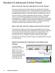
Scanner Control Power-Saving An energy saving feature is built into recent scanners models, in which the scanning lamp switches to power-saving mode when the scanner remains idle for a defined period of time. The scanner reverts to full power mode as soon as the Preview, Scan, Scan to, Copy, or E-mail button is executed. Aside from saving power, the feature also helps extend the service life of the lamp and prevents caking and deformation of your film original resulting from long exposure to lamp heat.
Define idle time interval for Power-Saving mode to take effect (60 minutes maximum) Uncheck this box to disable PowerSaving feature Compression Pane is enabled only if the scanner supports compression feature (see next page) Standard Mode Advanced Mode Compression Capability Compression is supported in certain models of scanners.
Scanner Information Click Scanner menu bar (Advanced mode, top) or Scanner icon (Standard mode, bottom), then choose scanner information from their respective menus to display the Scanner Information window ScanWizard 5 is constantly in touch with your scanner, monitoring the scanner availability, serviceability, as well as its make, and model.
ScanWizard 5 Help Features On-Line-Help from ScanWizard 5-Standard Control Panel Aside from on-line-help, the Help [ ? ] icon on the Title bar also provides access to Tutorial Guide program and SW 5-Standard version information. Click Help [?] icon to access on-line-help, Tutorial, and SW 5-Standard version information On-Line-Help To access on-line-help, click on the Help [?] icon. When the Help menu displays, choose Help.
On-Line-Help from ScanWizard 5-Advanced Control Panel The on-line-help of SW 5-Advanced mode is accessed through the Help menu on the Menu bar. The Help menu uses standard Windows conventions for obtaining on-line help. If you are not familiar with this procedure, refer to your Microsoft Windows user's guide. About This command provides same the information as in the Standard mode and displays the same splash screen shown in previous page.
Installing Your Image Editor If you intend to deliver your scanned image to an image editing program such as Adobe Photoshop, you also need to install that particular image editing program. The table below lists the image editing programs supported by ScanWizard 5.
2 Introduction to ScanWizard 5 Windows ScanWizard 5-Standard Control Panel SW 5-Standard is a single-window program that offers a simple and straightforward way of navigating a scanning session. It is a program designed for neophyte scanner users or for those who wish to accomplish scanning jobs quickly. Despite its simplicity, SW 5-Standard offers the essential tools for adjusting and enhancing your original image before final scanning.
The ScanWizard 5-Standard Main Window Click to perform final scan and select a destination for the scanned image Click to flip to ScanWizard 5Advanced mode Click for scanner info and power-save & compression control Click for on-linehelp/SW 5 Standard info/tutorial Click to select output image type (color, gray, or B&W) Click to prescan and preview scan material Click to define image resolution to match your target application Zoom up (+) button to magnify preview image Click to select a size (in as
On-Line-Help On-line-help can be accessed by clicking on the Help [?] icon near the right end of the Title bar (top bar of the SW 5-Standard window). Then Choose Help from the resulting menu. Click [?] icon to access on-line-help and choose Help from menu Balloon Screen Tips When you bring the mouse pointer over any of the capsule shaped buttons, a balloon-shape callout (containing hints on function and information of the button) will display.
ScanWizard 5-Advanced Control Panel The ScanWizard 5-Advanced Control Panel has four major windows consisting of the Preview, Settings , Information , and Scan Job Queue windows.
3 ScanWizard 5-Standard Control Panel Tutorial About the Tutorial This tutorial is embedded in the ScanWizard 5 driver program. To access the tutorial, you need run to ScanWizard 5-Standard. A powered-up scanner should also be connected and configured with your host computer (refer to the Installation Guide) before running the SW 5-Standard. You also need to place a scan material (original image) on your scanner to obtain a scanned output image at the end of the tutorial.
Basic Mouse and Keyboard Techniques This following explains some of the basic terms that are used in this manual. Term Meaning Click To quickly press and release mouse left button Double-click To click mouse left button twice in rapid succession Drag To hold down mouse left button while you move the mouse Click To click mouse left button twice in rapid succession Choosing and Selecting Items In any Windows application, the terms choose and select have different, and specific, meanings.
Launching ScanWizard 5-Standard Tutorial NOTE Be sure you have the original image (or scan material) properly placed on the powered on scanner before launching tutorial. Launching from an Image Application You will need to launch SW 5-Standard from an image editing application (e.g., Photoshop, PhotoImpact, etc.) if you wish to immediately deliver your output image to your application for further processing.
2. From the resulting dialog box, select Microtek ScanWizard 5 as the source of your image. Click Select to exit from the dialog box and to auto-save the image source setting. Launching ScanWizard 5-Standard from an Image Editor With the image source defined, you may directly invoke SW 5-Standard from the application (i.e., Photoshop) menu bar. Click on the File menu and select Import. From the resulting dialog box, choose TWAIN_32 ... (see figure below). Wait for the SW 5-Standard window to display.
Running from Start Menu To launch SW 5-Standard from Start menu, click on3 4 1. Start button 2 2. Program 3. Microtek ScanWizard 5 for Windows 4. ScanWizard 5 1 Running from Scanner Located Start Buttons If your scanner is equipped with either the "Go", or a combination of "Scan", "Copy", and "E-mail" start buttons, you may remotely launch SW 5-Standard from the scanner by pressing any of the available buttons. Note that these start buttons start SW 5-Standard as if it were launched from Start menu.
ScanWizard 5-Standard Tutorial Step-by-Step When the SW 5-Standard main window appears, click on the help [?] icon at top right of the window, and then choose Tutorial Guide from the resulting menu. Click (?) to access Tutorial and choose Tutorial Guide from menu Step 1 Preview Button You are now prompted (by the pointer position) to click the Preview button with a balloon screen tip on its function. Click the Preview button and observe your scanner starting to perform pre-scanning.
Step 3 Scan Type Button You are now prompted to click the Scan Type button while a balloon screen tip again provides hint on its function. Click Scan Type button and select into what image output category you wish to convert your original scan material. After the type of output image is selected, the pointer auto jumps to Purpose button or Step 4.
Step 6 Adjust Button The screen tip on this button suggests you may adjust (color toning, image brightness, etc.) the preview image to provide an enhanced output image. Click on the Adjust button and the SW 5-Standard image correction tool panel displays. Adjust image appearance by dragging the pellet button of each tool along its grooves. Observe the live update taking place with the preview image as you reposition each pellet.
"Scan" Button If SW 5-Standard was launched from an image editing application, the final scanning button is designated as Scan. Its sole function is to deliver the output image to the image application from which SW 5-Standard was launched. From your image processor, you may further edit and save the image. No option is available to deliver the output image to other destinations.
Enter a filename on the 'Filename' pane if the default filename does not suit you. Click the Save button to store the scanned output image Enter a filename here into your disk. If you do not assign a preferred directory, the image is saved by default in the 'Data' folder located under the same directory where your SW 5-Standard program is located, or in Windows\ Twain_32\ScanWiz5.
Attach to E-mail Choose E-mail from the menu if you wish to send out a copy of the output image as attachment to an e-mail. Notice that the Scan to button now becomes the E-mail button. When the Save As dialog box appears (with application check box enabled by default), click the Save button. Watch the final scan being performed and the resulting output image is saved to file. Then your e-mail editor (Netscape Messenger, Microsoft Outlook, etc.
Conclusion This ends your tutorial session. You may now go through it again to gain a deeper understanding of SW 5-Standard scanning steps and its basic features. Once you master the tutorial, go to Chapter 4 for an actual scanning session and for more details on SW 5-Standard not covered in this chapter.
4 Your First Scan with ScanWizard 5-Standard Launching/Exiting ScanWizard 5 Launch ScanWizard 5 as described in the preceding chapter (see page 3-3). Be sure to launch from your image processor if you wish to further edit or manipulate the scanned image with your application. Launch from your scanner start buttons, ScanWizard 5 Assistant button, or Start menu if you are going to save, print, browse, or e-mail the output image.
Previewing Your Original Scan Material By default, SW 5-Standard automatically detects and creates a preview image of your original in the SW 5-Standard preview window when you first launched the program. If you have disabled the auto preview function in the Preferences dialog box (see section on Setting Preference in SW 5-Standard in this chapter), you need to manually click the Preview button to prescan and preview your original scan material into the SW 5-Standard window.
Plotting a Scan Frame Area from the Preview Image To plot a scan frame, point at any corner of your intended scan frame. When the crosshair pointer appears, drag diagonally until you have the desired image selection enclosed in a frame, then release the mouse. Your actual scan frame border now turns into cascading lines. 5 Crosshair pointer Scan Frame Re-sizing a Scan Frame Ö You may adjust the size of your scan frame by pointing at any side of the scan frame.
Plotting a New Scan Frame You can always create another scan frame over an existing one or at another location of the same preview image. Like your previous scan frame, point at any corner of your intended new selection. When the crosshair pointer appears, drag diagonally until you have the new desired image selection enclosed in a frame. When you release the mouse button, the previous scan frame is discarded.
Resizing Main Preview Window Ö Another option to view the hidden area of a zoomed up image is to directly expand the size of the preview window. Simply point at the bottom-right corner of the window. When the diagonal 2-way arrow pointer occurs, drag the corner down diagonally to expand the window. If you have a small-size original (e.g., pocket book photo, match box, slide, etc.
Define Type of Output Image With your original properly displayed in the preview window, you have to specify the image category in which you wish to convert and output your original. To do this, click the Scan Type button. SW 5Standard offers four options of image conversion formats as shown at right. However, not all categories of the originals listed in the Original button menu can be converted into all of the listed conversion formats as shown in the table below.
Resolution of Output Image Click and use the resulting menu that pops up when you click the Purpose button to define the resolution for your output image. SW 5Standard provides default or predefined resolutions (based on the ultimate purpose or application, e.g., screen display, printing, etc.) that closely match with the image type of your original scan material (as defined under Original button menu).
Intended Size of Output Image By default, SW 5-Standard scans your original into an actual size (100%) output image. To change the output image dimension, click on the Scale Output button. From the resulting menu, select the predefined scaled size that best matches your intended image output dimension.
Output Image Setting Information As you perform adjustments and define various settings for the output of your original image (as reflected in the preview image), SW 5-Standard monitors and makes records of them. Part of the defined settings are displayed in the Status Bar (at the bottom of SW 5-Standard window) as soon as changes are made, while a separate and more comprehensive record of the changes are kept at the same time.
Final Scan and Output Image Destinations If you are satisfied with the appearance of your intended output image (as previewed from the preview window), you may now click the final scanning button. Note that the button may be designated as Scan, Scan to, Copy, or Email, depending on what environment in which you have launched your SW 5Standard (as explained below). ScanWizard 5-Standard Launched from an Application If you have launched SW 5-Standard from an image editing application (e.g.
For batch scanning with an auto document feeder (ADF) equipped scanner, you may provide root filename only. SW 5-Standard will auto-suffix such root filename with serial numbers to generate multiple filenames for the scanned and saved images in continuous sequence When your scanner is equipped with an automatic document feeder (ADF), ticking this check box will enable the auto-filename generation for the batch scan-to-file images Check to also invoke your application (Photoshop in this sample figure).
Routing the Saved Image to an Application If during the save-to-file-stage, you decide to further edit your output image with your image processor, or wish to send the image with your e-mail, or insert the image with your web browser for inclusion in an HTML document, just tick the check box (Send images to application..). Then select your application from the Combo Box (see figure in previous page). When you click on the Save button, final scanning and saving routine starts.
If an E-mail application is selected, multiple windows of the e-mail application will open - one for each of the output files. That is, if you have five output image files, five e-mail composer are opened with an image file attached to each of them. If an Internet Mail application was selected, the files are delivered to the Microtek e-mail editor in one batch as multiple attachments. Copy Output Image to Printer You need the Copy button to send an image directly to the printer.
Attach Output Image to an E-mail You need the E-mail button to attach the output image to your e-mail. If the button iscurrentlysetatE-mail, click button and the Save As dialog box displays. Otherwise, hold pointer on the button for about two seconds or until the selection menu appears (see top-left figure in previous page). Then select Email from the menu. The button immediately turns into E-mail button while the Save AS dialog box immediately displays with the application check box enabled by default.
Setting Preferences in ScanWizard 5-Standard When SW 5-Standard is launched for the first time, it will auto detect, by default, the type of scan material you have placed in your scanner and automatically performs a prescan on the original material. The prescan image is then placed in the preview area of the SW 5-Standard window. At the same time, it has a default window painted in "sky" blue tinted colors.
Uncheck to change prescan image preview from auto to manual operation Uncheck to change image detection and selection of the original scan material, and definition of output image type, from auto to manual operation Click to access Appearance dialog box (see below). Use it to repaint SW 5Standard window buttons and background, and to relocate buttons pane location to accommodate left handed user (see below).
Saving Your Favorite Color Scheme When you saved the custom color pattern you have just defined, the pattern is added at the bottom of an existing list of color patterns under Scheme menu (see figure at right). When deleting color pattern items from the Scheme menu, you can only delete the user defined items. The default items can not be deleted.
4-18 Microtek ScanWizard 5
5 Your First Scan with ScanWizard 5-Advanced Launching/Exiting ScanWizard 5-Advanced Launch ScanWizard 5 as described in Chapter 3 (page 3-3). Be sure to launch from your image processor if you wish to further edit or manipulate the scanned image with your application. Launch from your scanner start buttons, ScanWizard 5 Assistant button, or Start menu if you are going to save, print, browse, or e-mail the output image.
The Main Windows of ScanWizard 5-Advanced Control Panel The ScanWizard 5-Advanced Control Panel has four major windows consisting of the Preview, Settings , Information , and Scan Job Queue windows.
Operating ScanWizard 5-Advanced Control Panel NOTE Be sure you have the original image (or scan material) properly placed on the powered on scanner before launching ScanWizard 5. 1. Perform a low-resolution preview. Click on the Overview button to scan an image. Scan Frame tool Scan button Prescan button Overview button Preview area 2. Select the required scan area. Click on the Scan Frame tool.
3. Select the image type. Select the image type to be processed and scanned. You can put one image type on the scanner and scan that in its original form, or you can scan it in another form altogether. For example, you may have a color photo and scan it in the same color mode, or you may scan it as a grayscale or line art image. Resolution edit box Image type Output size Image correction tools 4. Set output resolution and Output Size.
6. [Optional] Set Advanced Image Correction (AIC). Click on any of the Advanced Image Correction (AIC) tools in the Settings window. These tools allow you to adjust image features such as brightness and contrast; black and white points; tone curve; hue or saturation; and lets you apply various filters for special effects. 7. Perform the final scan. Click on the Scan button to scan your selected image. The scanned image is delivered to your application.
Scanning a single-bit image (line art or B&W diffusion) 1. Perform a low-resolution preview. Click on the Overview button in the Preview window. In moments, a preliminary view of the image appears in the preview area. Prescan button Frame tool Scan button Overview button Preview area 2. Select the required scan area. Click on the Scan Frame tool. With the pointer now a crossbar, move to the image and define the scan frame (by holding down the mouse and dragging it to draw a box).
3. Select the image type. From the Settings window, at the Type drop-down menu, make your selection. Image type Threshold button Image correction tools 4. • Choose Line art if you are scanning purely black or white images with no shades of gray, such as pen-and-ink drawings, logos, and sketches. Line art also applies if you're scanning an image with just one color (like a mechanical drawing or blueprint). • Choose B&W Diffusion if you are scanning black or white images with shades of gray.
Scanning a grayscale image 1. Perform a low-resolution preview. Click on the Overview button in the Preview window. In moments, a preliminary view of the image will appear in the preview area. Prescan button Scan Frame tool Scan button Overview button Preview area 2. Select the required scan area. Click on the Scan Frame tool. The pointer now becomes a crossbar, move to the image and define the scan frame (by dragging the mouse to draw a box).
3. Select the image type. From the Settings window, select the image type to be processed and scanned. Image type Image correction tools 4. Set Output Resolution and Output Size. Output resolution: Enter a resolution setting in the Resolution edit box, then press Enter. Output size: Enter the Output width/height value, indicating the relationship of the input dimension, scaling, and the resulting image size.
5. [Optional] Perform a high-resolution preview for the current selected scan area. Click on the Prescan button to see the image in high resolution. 6. [Optional] Set Advanced Image Correction (AIC). Click on any of the Advanced Image Correction (AIC) tools in the Settings window. These tools allow you to adjust image features such as brightness and contrast; black and white points; tone curve; hue or saturation; and lets you apply various filters for special effects. 7. Perform final scan.
Scanning an RGB color image 1. Perform a low-resolution preview. Click on the Overview button to preview image. Prescan button Scan Frame tool Scan button Overview button Preview area 2. Select the required scan area. Click on the Scan Frame tool. The pointer now becomes a crossbar, move to the image and define the scan frame (by dragging the mouse to draw a box). The scan frame will be enclosed by dotted lines and will be the actual scan area when you click on the Scan button.
3. Select the image type From the Setting window select the image type to be processed and scanned. Image type Resolution edit box Output size Image correction tools 4. Set Output Resolution and Output Size Output resolution: Enter a resolution setting in the Resolution edit box, then press Enter. Output size: Enter the Output width/height value, indicating the relationship of the input dimension, scaling, and the resulting image size.
5. [Optional] Perform a high-resolution preview for the current selected scan area. Click on the Prescan button to see the image in high resolution. 6. [Optional] Set Advanced Image Correction (AIC). Click on any of the Advanced Image Correction (AIC) tools in the Settings window. These tools allow you to adjust image features such as brightness and contrast; black and white points; tone curve; hue or saturation; and lets you apply various filters for special effects. 7. Perform final scan.
Important scanning notes If you are not familiar with the scanning process, you may wish to review the preceding pages first on the individual scanning tasks to get a feel for the software and how it works. Also, if some of the concepts discussed in these pages are not familiar to you, refer to Chapter 6, Reference section of the manual for more detailed discussion. For previews and scans Using the Scan Frame tool Familiarize yourself with the Scan Frame tool.
Using the Prescan action button Familiarize yourself too with the Prescan button, which is ideal for enlarging the preview image and previewing it in detailed, high resolution. The enlarged view obtained from prescan is not the same as the view obtained from the Zoom tool, which is simply an enlarged pixilated view in low resolution.
Fixed Scan Frame If checked, the size of the scan frame remains the same as the current one. You may, however, move the scan frame in the Preview window. For previews and scans Fixed Output Size If checked, the image size (disk space) and width/height of the output size remain the same. The output size determines the width and height of your image when output to a device such as a monitor or printer. The output size can be changed only if this option is unchecked.
For image correction • Use the powerful image correction tools to improve your image if necessary, and familiarize yourself with the features of the Advanced Image Correction (AIC) dialog box. Image correction tools While in the AIC dialog box, you can see thumbnails of the image, make image corrections there, and see the effects of the changes (“before” and “after” versions ) in realtime. If the Preview checkbox is checked, these effects are reflected in realtime in the Preview image.
You can also switch from one tool to another within the AIC dialog box. Familiarize yourself too with the various action buttons in the AIC dialog box and how they work. This is important.
For scan job queue • Use the flexibility provided by the scan job functions to manage your scan jobs. With the Scan Job Queue Window, you can create new scan jobs, copy settings for a duplicate scan job, save scan jobs as templates, and load the scan jobs templates for future use. • To master the intricacies of the scan job functions, familiarize yourself with the usage of the Scan Frame tool and the Smoked Glass Background feature, both of which are linked to the functions of the scan job.
Scaling the view of an image Click on the Overview button. When the preview image appears, do either of the following: Option 1: Enlarging the view 1. Click on the Zoom tool. The cursor will change to a magnifying glass pointer with a plus (+) sign in it. 2. Move the pointer inside the image and click. The area where the pointer is positioned is zoomed in, enlarging your view of it.
Option 2: Reducing the view To reduce your view of the image after it was magnified: While holding down the Shift key on your keyboard, move the pointer to any portion of the image, and click on the mouse. The magnifying lens will show a minus sign (-) in it, at the same time reducing your view of the image. Clicking successively will continue to reduce the image until it is scaled down to its original size. 1. In the Preview window, choose the Show Info window command from the View menu. 2.
Correcting images The image correction tools are located in the Settings window. Click on any of the image correction tools to adjust your image. The AIC dialog box will then appear.
Using the Advanced Image Correction dialog box When you click on any of the image correction buttons in the Settings window, the Advanced Image Correction (AIC) dialog box appears. In this box, you can do the following: 1. See a thumbnail of the image captured by your scanner, and see how the image changes when adjustments are applied to it. The “before” and “after” images are the left and right thumbnails in the dialog box. 2.
Final Scan and Output Image Destinations If you are satisfied with the appearance of your intended output image (as previewed from the preview window), you may now click the final scanning button. Note that the button may be designated as Scan, Scan to, Copy, or Email, depending on what environment in which you have launched your SW 5Standard (as explained below). SW 5-Advanced Launched from an Application If you have launched SW 5-Advanced from an image editing application (e.g.
For batch scanning with an auto document feeder (ADF) equipped scanner, you may provide root filename only. ScanWizard 5Advanced will auto-suffix such root filename with serial numbers to generate multiple filenames for the scanned and saved images in continuous sequence Tick this check box to enable the autofilename generation for the scan-tofile images Check to also invoke your application (Photoshop in this sample figure).
Routing the Saved Image to an Application If during the save-to-file-stage, you decide to further edit your output image with your image processor, or wish to send the image with your e-mail, or insert the image with your web browser for inclusion in an HTML document, just tick the check box (Send images to application..). Then select your application from the Combo Box (see figure in previous page). When you click on the Save button, final scanning and saving routine starts.
If an E-mail application is selected, multiple windows of the e-mail application will open - one for each of the output files. That is, if you have five output image files, five e-mail composer are opened with an image file attached to each of them. If an Internet Mail application was selected, the files are delivered to the Microtek e-mail editor in one batch as multiple attachments. Copy Output Image to Printer You need the Copy button to send an image directly to the printer.
Attach Output Image to an E-mail You need the E-mail button to attach the output image to your e-mail. If the button is currently set at E-mail, click the button and the Save As dialog box displays. Otherwise, hold the pointer on the button for about two seconds or until the selection menu appears (see top-left figure in previous page). Then select E-mail from the menu.
6 Reference to ScanWizard 5-Advanced This chapter explains in details all the features offered by ScanWizard 5Advanced Control Panel. The reference information is organized into four parts, each showing the four major windows of the program and their respective detailed functions.
The Main Windows of ScanWizard 5-Advanced Control Panel ScanWizard 5 consists of four major windows: Preview, Settings, Information, and Scan Job Queue. The four windows appear automatically after the ScanWizard 5-Advanced Control Panel is started up. The Scan Job and Information windows appear when you bring up ScanWizard 5 at the first time. You may hide or show them from the View menu and click on the commands Show Scan Job Window and Show Info Window.
Running ScanWizard 5-Advanced Control Panel To invoke ScanWizard 5, click on Start , Programs , select Microtek ScanWizard 5 for Windows , then ScanWizard 5 . Alternatively, you may start up your image-editing software first. When the application opens, choose the command for running ScanWizard 5 from your application. The Preview and Settings windows will always appear automatically whenever the SW 5-Advanced is started up.
The Preview Window The Preview window is the most prominent window of the four major windows, and it includes the various commands and tools for controlling the scanner. Elements of the Preview window 1 2 4 5 3 6 7 8 1 The Menu Bar includes the different menus for setting up the scanner (Scanner menu), controlling view options (View menu), customizing the software (Preferences menu), Image Correction function (Correction menu), and accessing on-line help (Help menu).
The Menu Bar Reference: The Preview window 6-5
The Scanner Menu The Scanner Menu lets you: • Show your scanner model or select a scanner if you have multiple scanners • Get information about your scanner • Get information about the SCSI chain Scanner Model The top of the scanner menu displays the scanner model you're using and its Scanner ID. If you have multiple scanners on your system, all the scanners are shown with their respective Scanner IDs, and the current scanner is indicated by a check. Only one scanner can be accessed at a time.
Scanner Probe This command allows you to see the SCSI devices on your SCSI chain and the Scanner ID number of the devices. By default, all numbers are selected by the check boxes. To allow ScanWizard 5Advanced Control Panel to start up more quickly, select only the boxes that match the Scanner ID of your scanner (or scanners, if you have multiple scanners on your system). This will make the ScanWizard 5 bypass the numbers for your other devices and focus effort on simply detecting scanners.
Exiting ScanWizard 5-Advanced Control Panel To exit ScanWizard 5, click on the close box on the upper right side of the Preview window.
The View Menu The View menu lets you: • Get an overview or prescan view of an image • Resize the Preview window • Show or hide the Information and Scan Job windows Overview Image This command switches to Overview mode, lets you view the Overview image among the scan jobs. The Overview is a preview of your image as defined by the parameters set in the Overview Setup command (in the Preferences menu).
Prescan Image By default, the Prescan Image Command does not exist, unless you press the Prescan button. Each prescan image belongs to the respective scan job. In the above screen, the Untitled1 Prescan Image is resulted ever since you clicked the Prescan button for a scan job named Untitled1. When you select the prescan image item (e.g., Untitled1 Prescan Image), the preview window switches to the Prescan mode.
Resize Window to Fit This command adjusts the Preview window to fit the Overview area. In the example below, the Preview window is larger than the Overview area, as denoted by the empty space below the vertical ruler. In other instances, the Preview window may also exceed the Overview area if you manually enlarged the Preview window (by dragging on the resize box). To utilize window space more efficiently, use this command to resize the Preview window.
Show/Hide commands These commands allow you to switch between showing or hiding the Scan Job, Information windows, and Status Bar on your screen. To use this feature, choose the correct command from the View menu for viewing a window. When the window appears, you can hide it by choosing the particular Hide command for it. The Setting Window always comes with the Preview window. You may bring the Setting Window to the front by choosing it from the View menu.
The Preferences Menu The Preferences menu lets you: • Choose the correct scan material • Set up color matching system • Set up White/black point parameters • Hide/show auxiliary cursor lines • Set up Overview mode parameters • Set up Prescan mode parameters • Fine-tune monitor gamma values • Invert images on the screen • Further settings Reference: The Preview Window 6-13
Scan Material This command allows you to select the correct scan material. Scan materials can be classified into three types: • Reflectives, such as photographs or prints. • Positives, such as slides. • Negatives, such as the negative film you use for your camera. The default scan material depends upon the scanner you're using, and the choices available to you in the Scan Material submenu will also depend on your equipment.
The Scan Material Status icon Another way to access the Scan Material menu is to use the Scan Material Status icon, located to the right of the Scan button. Scan Material Status icon The appearance of the Scan Material icon changes, depending on whether your scan material is reflective, positive, or negative. • If you're scanning a reflective (such as a photo or print), this icon will appear in its normal form like an ordinary icon.
Color Matching Setup To keep color consistency between the scanner, monitor, and printing device, ScanWizard 5 applies Kodak CMS (Color management system) with ICC (International Color Consortium) profile standards. For more information on Color Management System, see Appendix C. Color Matching Set Up command lets you select the correct ICC profile for matching with your color monitor and color printer. When you install ScanWizard 5, the default profiles of color monitor and printer are set to sRGB.
RGB Destination This feature lets you select the RGB output device (e.g., display monitor, or RGBbased printer) for matching RGB Color family images (including RGB colors, 48bit RGB colors, and 256 colors image types). Display Using Monitor Compensation This option controls how the RGB destination data is displayed. If unchecked, the RGB data are displayed directly to the monitor. If checked, RGB data are first compensated according to the selected monitor type, then send to the monitor.
Select the profiles you need, then click on the Open button to load the profiles to ScanWizard 5. This process takes a while for initialization. Note: When you purchase color monitor or color printer, check to make sure your supplier provides the corresponding ICC profiles. Info This command displays basic profile information for the current selected devices.
White/Black Points Setup White point is a reference point that specifies the lightest area in an image, making other areas to be adjusted accordingly. Likewise, black point is the darkest reference area. Auto White Point Clipping Lets you set the percentage of pixel in the highlight region to be truncated. Effective only when “Auto White/Black point” option is selected in the AIC dialog box. Auto Black Point Clipping Lets you set the percentage of pixel in the shadow region to be truncated.
Cursor Auxiliary Lines This command allows you to create horizontal and vertical grid lines with your cursor to help define a scan frame precisely. Using the grid lines, you can also read the measurements off your ruler more easily. Cursor auxiliary lines on the x and y axis To use this feature: 1. Choose the Cursor Auxiliary Lines command in the Preferences menu. From the submenu that appears, select how the cursor lines will appear.
2. Click on the Frame tool. To see how the cursor lines work, draw a scan frame. Click on the top left corner of the image as your starting point, then drag down to form a scan frame. As you draw the scan frame, cursor lines will appear to help you draw the scan frame precisely. When you release the mouse, your scan frame will be aligned with the cursor lines. Click on the Frame tool, then define a starting point. Cursor lines appear to the top and left of the image.
Overview Setup Specifies overview scanning speed options and the overview area for executing the Overview command. Fast Overview The Fast option supports faster scanning with the sacrifice of overview image quality; on the contrary, if Fast Overview is unchecked, Overview scanning speed is slow, but it obtains better overview image quality. Overview Area Choose Maximum Size, other fixed dimensions, or choose Custom Size then enter the required dimensions.
Prescan Setup This command allows you to set the parameters of scanning a prescan image. Major difference between Overview and Prescan is, Overview button scans the area specified in the Overview Setup command getting a low resolution preview image; where Prescan button only scans the selected scanning frame, resulting a more detailed preview image. When the Prescan Setup dialog box (below) comes up, click on the option you need or specify your parameters.
Monitor Gamma Setup The Monitor Gamma Setup command lets you compensate linear intensity of the monitor, making them consistent between preview image and the final scanned image. Monitor Gamma Check this box to enable monitor gamma value setting. When the monitor gamma option is checked, click the up/down arrow buttons, making gray-level of the two boxes as close as possible. Click OK to confirm.
Invert This command creates a negative of an image. The Invert effect is applied to all scan jobs, not just the selected scan job. When an image is inverted, the brightness value of each pixel is converted to the inverse value on the 256-step color values scale. For example, a pixel in a positive image with a value of 255 is changed to 0, and a pixel with a value of 5 is changed to 250. Original Invert To use this feature: Choose the Invert command in the Preferences menu.
More command The More command lets you specify rarely used, miscellaneous parameters. Keep Overview Image If checked, the image which is prescanned in the overview command remains on the screen until next image acquisition is performed. If unchecked, when you exit from ScanWizard 5, the overview image is deleted. Keep All Prescan Image If checked the image which is prescanned in the prescan command remains on the screen until next image acquisition is performed.
scan frame or applying image-correction controls. This way, the changes can be seen more clearly and stand out from the rest of the material. (See the next section for more details. ) Current scan frame (with pulsing lines) Part of image not in any scan frame and also hidden by smoked glass background Scan Quality selection During scan, you have these selections: Speed, Quality, and Best Quality. Speed Higher scanning speed results lower image quality.
Working Directory Lets you specify a place to store temporary working files (e.g., scan job files) during ScanWizard's session. If the directory you specify is not found or does not exist, a warning message appears, and ScanWizard 5 will create a new one for it. If the computer is shared to use by many persons, each person may specify the respective working directory of his own.
The Help Menu The Help menu lets you access on-line help for ScanWizard 5-Advanced Control Panel. The Help menu uses standard Windows conventions for obtaining on-line help. If you are not familiar with this procedure, refer to your Microsoft Windows user's guide. About This command gives you information on the ScanWizard 5-Advanced Control Panel scanning software. ScanWizard 5 is also referred to in the About screen as the ScanWizard 5 scanner controller.
The Tool Buttons Frame Magnify Glass Pane Color Picker 6-30 Microtek ScanWizard 5
Scan Frame tool The Frame tool lets you create a scan frame or multiple scan frames in the preview image, which is the active area on which controls and commands can be applied. The Frame tool can also be used to create multiple scan frames, but only one can be current at a time; the current scan frame is indicated by a marquee (marching ants, or dotted boarders). The current scan frame can be more easily distinguished if you turn on the Smoked Glass Background command (in the Preferences menu).
Scan Frame Keyboard Shortcuts To get a better controls of scan frame settings, use Ctrl and Shift keys on your keyboard. Ctrl key Holding down the Ctrl key and drag the marquee results a square selection. Shift key Holding down the Shift key and drag the marquee generates a new frame for a scan job. A more detailed table is listed below. 6-32 Function Keys Result Move/Resize click+move click+drag Ctrl+click+drag Move scan frame. Resize scan frame. Toggle between “Keep Square” and “resize”.
To use the Frame tool: 1. Click on the Frame tool. 2. Move the pointer (now a crossbar) to the preview image, and draw a frame enclosing the area to be selected. When you release the mouse, the scan frame will be in a marquee. To make multiple scan frames (which would add scan jobs), hold down the Shift key and drag the mouse. For more information on scan jobs, refer to the Scan Job section of the Reference. 3.
Magnify Glass tool The Magnify Glass tool enlarges your view of the preview image, allowing you to set the scan frame with greater precision if you need to. Only your view of the preview image is changed; the actual size of the image remains unaffected. Each click of the Magnify Glass tool magnifies or reduces by a factor of 2. Thus, the magnification levels increase from 100% to 200%, to 400%, and to the maximum 800%.
Pane tool The Pane tool lets you scroll through a preview image, allowing you to move parts of the image into view. The Pane tool can be used for zoomed-in images (enlarged through the Magnify Glass tool), or images not included completely within the frame of the preview window. (for instance, if your preview image is 7 inches wide and you resized the width of your overview/preview window to only 3 inches). Zoomed-in image Scrolled image To use the Pane tool: 1. Click on the Pane tool. 2.
Color Picker tool The Color Picker tool allows you to sample color from an area in an image, also useful for designating shadow or highlight point. With the Color Picker tool, you can determine the color values for any pixel in an image. When you click on the Color Picker tool, and pan over a pixel, the value for that pixel is displayed in the Information window, based on the sample size selected in the Information window.
To change the sample size of the Color Picker: 1. Open the Information window by choosing the Show Info Window command in the View menu. 2. Click on the Sample Size button, located to the right of the RGB values in the Information window. 3. Choose your options. Select the sample size. For instance, the 1 by 1 option will display the value of one pixel — the one in the middle of the Color Meter Display. The 3 X 3 option reads the average value of a 3-pixel by 3-pixel area.
Action Buttons The Overview button scans a low resolution preview at a size specified in the Overview Setup command. The Prescan button performs high resolution preview for the selected scan jobs. The Scan button lets you scan the image in your scanner and delivers it to your image-editing software. The scanned image is based on the specifications you have chosen in the Settings window and on controls you may have applied to the preview image if a preview was performed.
Rulers The rulers on both sides of the preview window help you with operations that need precise measurement and alignment of your image. The unit of measurement in the rulers is determined by the unit of measurement you have selected. This can be done either in the Image Dimension controls, located in the Settings window, or by clicking on the ruler unit button at the 0,0 point of the rulers in the Preview window.
Preview Area The preview area is where the preview image appears. The dimension of the preview area varies, depending on your scanner model. The size can be changed, however, through the Overview Setup command in the Preferences menu. You can increase the size of the preview area to see more detail in your image, or you can reduce the preview area to save on memory. For details on how to change the size of the preview area, refer to the Overview Setup command in the Preferences menu section.
The Settings Window The Settings window contains the parameters for outputting your scanned image for the current scan job and includes the advanced image correction tools of the program. Elements of the Settings window Resolution edit box: Lets you enter a resolution value in which your image will be output (not scanned). Image Dimension controls: include various parameters for specifying scan frame width and height, scaling, output width and height, and unit of measurement.
Output Image Parameters The Output Image Parameters include the various controls that determine how your image is scanned and processed. The Output Image Parameters include: • Type • Resolution • Unit Selection • Image Dimension controls • Image Orientation controls Type (Image Type or Scan Mode) The Type menu determines what your resulting scan will be. It does not refer to the original image mode.
• Customized 256 color option lets you select the attributes of indexed color. If this option is selected, the following dialog box displayed. Palette Lets you choose the method of creating color palette table. “Uniform” uses 6-6-6 levels fixed color palette table, independent of the contents of the 24-bit RGB image. By default, the “Adaptive” is selected, this option creates color palette table from commonly used areas of the color spectrum that appears in the image.
Resolution Resolution in the Settings window refers to the desired resolution for outputting the image to a device, such as a monitor or printer. It does not refer to the resolution in which the image is scanned. To set your resolution: Enter a resolution setting in the Resolution edit box, then press Enter. If the value you enter is too low or too high, the minimum or maximum resolution value is entered for you instead. According to the image type you select, default resolution is displayed.
Unit selection The unit of measurement for resolution is in ppi (pixel per inch) or lpi (lines per inch). Lpi settings are dimmed if the ruler unit is in pixels, and vice versa for ppi. To select your option: • Choose lpi (1x) if you know precisely the resolution you need for your image. Or, in case of Stochastic halftone and contone (continuous tone) printing. • Choose lpi (1.5x) to produce resolution that is one and one-half times the screen frequency.
Image Dimension controls These controls allow you to adjust the various factors that affect the image, including the width and height of your image when it is first scanned (Scan Frame), the scaling factor, and the dimensions of the image in final output. 1. Scan Frame (input) x Scaling = output: This mathematical formula indicates the relation of the input dimensions to scaling and how these factors affect image dimensions when the image is scanned.
4. The Unit of Measurement allows you to select your unit of measure. The options include inch, centimeter (cm), millimeter (mm), point, pixel, and pica. 5. The Size indicates how big the file will be when you accept the dimensions shown in the edit boxes, together with the resolution setting that you selected. Size is calculated automatically. Rotate and Flip tool Click the “F” icon to bring up rotate and horizontal image flip selections. The “F” icon represents the current selected orientation job.
How to use the Input-Output dimensions The Input-Output dimensions consist of four edit boxes: Scan Frame width, Scan Frame height, output width, and output height. These edit boxes are linked to the use of Fixed Scan Frame, and the boxes may or may not be edited depending on whether the Fixed Output Sized is checked or not. Below are the details.
Advanced Image Correction Tools White/Black Points tool Tone Curve tool Brightness & Contrast tool Color Correction tool Filter tool Descreen tool Available Image Correction Effects ScanWizard 5 automatically locates all default settings and the settings you have made from a specific directory, then include them to the dialog box. Image correction effects do not apply to all image types. Unsupported image corrections are grayed out in the menu.
Introducing the Image Correction tools With the image correction tools, you can adjust the characteristics of your image right from within the ScanWizard 5. The image correction tools in ScanWizard 5 save you time and provide you with the needed flexibility to adjust images right within the scanning software. Although you can use all the image correction tools, you don't need to use everyone of them to achieve a great image. Perhaps all that's needed is a change in the shadows or gamma curve.
The Action Buttons in the AIC dialog box The Action buttons in the AIC dialog box carry out a specific action. 1:1 Thumbnails If checked, size of the thumbnail is about the same as the image shown in the Preview window. If unchecked, the image size appears fit into the shown dialog box. Hide Thumbnails If checked, the “before” and “after” thumbnails becomes hidden. To redisplay, click the “Up” arrow at the left side of the dialog box.
The OK button Clicking on this button will apply whatever Image Corrections you have performed on the current scan job, and close the AIC dialog box. Example : If you increased brightness, changed the saturation, and then clicked OK, all the changes are applied, and you exit the AIC dialog box. The settings are changed as Customized status. The Cancel button Clicking on this button will cancel out all image correction changes you have made to the current scan job, and then close the AIC dialog box.
The Revert button Clicking on this button cancels out the changes you made with the current image correction tool. This means that if you used several tools (and achieved a look that is the cumulative effect of all the tools), using Revert will cancel the effect of only the current tool and preserve the effects of the other preceding tools.
To retrieve user-defined AIC settings From Settings window, select the AIC settings you have made from the respective AIC command. Example: Suppose the White/Black Point settings of your input (e.g., 24-bit color) is available for choosing. To remove user-defined AIC settings From Settings window, choose the AIC function, then select the Remove Settings item. A Settings dialog box appears. Select the Settings you want to remove, click the Remove button.
White/Black Points tool For color and gray images, this tool allows you set white/black points; for lineart image, it carries out threshold adjustment feature. The White/Black Points dialog box (Color/Gray image) Histogram Pickers Sliders Auto Histogram The histogram is obtained from the scanned image material in the current frame. The darkest pixels are at the left, and the lightest pixels are at the right.
Sliders If you would like to set white/black points by yourself, then drag the Sliders to adjust Black and White points of an image. Pickers Instead of the sliders, you may use the Black and White pickers to set the Black and White point values from the preview image. Auto button Clicking this button lets ScanWizard 5 automatically judges the darkest and whitest points, and clips excessive white/black points.
The Threshold dialog box (Line-art image) For line-art image, the White/Black point setting becomes as threshold setting. Histogram Sharpen Threshold The threshold values are in the range of 0 through 255. Sharpen This option lets you further enhance line-art image quality, if your original lineart material appears blur, for example, the text printed by inkjet, dot matrix printer, or contains text with small point sizes.
Tone Curve tool The Tone Curve tool lets you control the gamma, which measures the intensity affecting the mid-level grays (midtones) of an image. Gamma is commonly used to describe the relationship between output density to the original density across the mid-tones. Adjusting the gamma lets you change the values of the middle range of gray tones without dramatically altering the shadows and highlights.
Scan Original brightness value 8-bit color/Gray 0 - 255 10-bit color/Gray 0 - 1023 12-bit color/Gray 0 - 4095 When the curve is moved up or down, the relationship between input value and output value changes accordingly. • In areas where the curve is moved down, pixels in that portion of the image are darkened. • In areas where the curve is moved up, pixels in that portion of the image are lightened. Contrast in an image can be seen by the angle of the line.
Sample images and their curves Here, the original curve is a straight diagonal, indicating that input and output values are equal. Here, points along the curve have been moved up, so that pixels are lightened as they are plotted to new points. For RGB image type, the net effect creates a lighter image. For gray scale image type, the net effect creates a darker image. Here, points along the curve have been moved down, so that pixels are darkened as they are plotted to new points.
The Curve screen Method Channel Curve Curve buttons Curve The Curve is a graphic representation of the gamma, showing scanner input from dark on the left to light on the right. Method The Method sets the kind of curve you wish to have. Select from Line, Curve, or Gamma. Line Curve Gamma Channel The Channel allows you to choose the color or gray channel in which the gamma will be affected.
Input/Output/Zoom: • Input shows the input value of wherever the cursor is pointing on the horizontal axis of the curve. In the example above, the cursor is pointing to the middle of the curve, with a value of 136 on the 0-to-255 pixel scale. • Output shows the output value of wherever the cursor is pointing on the vertical axis of the curve. In the example above, the cursor is pointing to the exact middle of the curve, with a value of 119 on the 0-to-255 pixel scale.
Using the Curve buttons The Curve buttons allow you to modify the curve in the Curve screen. The tools are the Pointer, Zoom Frame, and Hand. • Use the Pointer tool to define points in the curve that will be modified. When you click on any point in the curve, a control point appears to mark your position. To remove a control point, drag it off the graph. Pointer Original curve Zoom Frame New control points • Use the Zoom Frame tool to zoom in on a particular point in the curve.
Using the Curve tool 2 1 4 3 6 5 1. 2. Choose the channel in which the curve will be modified. • Select All to modify gamma in the color channels of the image simultaneously. Depending on the image type you select, the color channels can be “All, R, G, B”. • Select color channels individually (red, green, blue) to modify gamma in that particular color channel. • For grayscale scanners, only the gray channel is available.
5. 6. Click on an action button. • Click OK to accept changes and exit the AIE dialog box. • Click Cancel to abandon all changes and exit the AIE dialog box. • Click Reset to restore settings to original default values. • Click Revert to cancel the effect of the current image-enhancement tool. To save a curve, click on the Save As button. A dialog box will appear. • Save the curve in Microtek formate.
Brightness and Contrast tool The Brightness and Contrast tool changes the brightness, contrast of the entire image. Brightness The Brightness control lets you change the brightness setting. Too much brightness can make an image look washed out. Contrast The Contrast control lets you change the contrast setting. • High contrast can make an image look like a photocopy of a picture with little or no gray shades. • Low contrast can make an image look dull and flat.
Color Correction tool This tool changes hue and saturation of the image. The Color Correction tool lets you click on the preview image to remove the unwanted color cast. The parameters needed to balance the clicked pixel is reflected on the color wheel, angle and radius values are updated accordingly. The Color Correction tool is useful when the image has a particular color cast and you wish to remove the cast to make the image look neutral.
Using the Color Correction tool 1 2 3 6-68 1. To change the hue of an image, move the pointer in the color wheel to its new color position in the wheel. 2. To change the saturation of an image, drag on the saturation bar. Dragging the slide bar to the left decreases saturation; dragging it to the right increases saturation. 3. Click on an action button. • Click OK to accept changes and exit the AIC dialog box. • Click Cancel to abandon all changes and exit the AIC dialog box.
Filters tool The Filters tool lets you apply or create special effects to your images. The filters include Blur, Blur More, Sharpen, Sharpen More, Edge Enhancement, and Emboss. The image you obtain in the preview when you use the Filters tool may differ from the way the image will appear when you scan it in. This depends on your resolution, and the higher the setting, the less obvious certain filters (like Blur) will have. To select the filters: Choose the filter from the filter pop-up menu dialog box.
Blur filters The Blur filters eliminate noise in the parts of the image where significant color transitions occur. The Blur filters decrease the contrast between adjacent pixels, making the image appear hazy and out of focus. • Blur smooths out the transitions by lightening pixels next to the hard edges of defined lines and shaded areas. • Blur More produces an effect three or four times stronger than Blur.
Edge Enhancement filter The Edge Enhancement filter gives greater contrast to edges. The filters can do this because edges are usually areas in an image where gray or color levels change abruptly. It is best to use this tool for improving geometrical contouring shape. Original Edge Enhancement Emboss filter The Emboss filter makes a selection appear raised or stamped by suppressing the color within the selection and then tracing its edges with black.
Descreen Descreen allows you to remove moiré patterns in images. A moiré is an undesirable pattern in printing that results from incorrect screen angles of overprinting halftone. Moiré usually result when you scan images taken directly from a magazine (instead of scanning a continuous glossy photographic original or a transparency). Before Descreen After Descreen To use Descreen: 1. Click on the Descreen pop-up menu. 2. When the Descreen menu comes up, select the screen for your needs.
The Information Window The Information window is a floating window that provides preview image information at the cursor location. It also allows you to change zoom levels directly, in much the same way like using the Magnify Glass tool in the Preview window. To display the information window, click on the Show Info window command in the View menu in the Preview window.
Zoom Level Display The Zoom Level Display shows the magnification levels possible from 100% to a maximum 800% view. Cursor Locator The Cursor Locator shows where the cursor is on the coordinates along the x (horizontal) and y (vertical) axis, based on the unit of measurement selected for the rulers. This feature is useful for operations that require very precise measurements and alignment. Output value This data indicate the output values of the selected image type.
Sample size button The Sample Size button lets you choose how extensively the color information will be read — whether it will apply to a single pixel or an averaged area. Clicking the Sample Size button displays the sample size. The values as a whole represent color information for the sample size selected in the Sample Size button. For instance, if you chose 3 x 3 as your sample size and your R value reads 23, that shows your red value of 23 is the average of a 3-pixel by 3-pixel area.
The Scan Job Queue Window The Scan Job window provides several key functions in managing your scan jobs. A scan job is simply a task that you designate the scanner to process and scan. For instance, when you first preview an image, the image as a whole has its own parameters (its own brightness and contrast setting, resolution, etc.). The whole image can be treated as one scan job, or you can select part of the image, apply different parameters to it, and treat that as a separate scan job.
Multiple Selections Duplicate, Delete, and Check buttons allow multiple selections. For multiple random selection, holding down the Ctrl key, then click the scan jobs respectively; for sequential selection, click the “begin” scan job, then holding down the Shift key, click the “end” scan job. The highlighted scan jobs are selected.
How to read the Scan Job window 3 1 2 1. The example above shows three scan jobs. • The first scan job, entitled Untitled1, is a color image. • The second scan job, entitled Graylevel is a grayscale image. • The third scan job, entitled 24bit color, is a duplicate that shares the settings of the first scan job. The current scan job is the third scan job (24bit color), as it is highlighted.
The New button The New button lets you create a new scan job; the new scan job will have default settings. This feature allows you to create as many scan jobs as you wish, and each scan job can then have its own settings. A scan frame may already be present after you click on the Overview button and the preview image appears. You can then simply grab one of the corners of the scan frame and drag towards the left to form the scan frame described above.
3. Click on the New button in the Scan Job window. When a dialog box comes up, give a title to the new scan job, then click OK. In this example, we will call the new scan job Untitled2. The Scan Job window will now have two titles. At the same time, a new scan frame appears in the preview window. New scan frame appears with the addition of a new scan job. Two titles now appear in the Scan Job window. 4. Draw the second scan frame around the right half of the image.
5. With the title bar in the Scan Job window highlighting the second scan job, go to the Settings window, then choose Grayscale in the Type box. Next, go to the Preferences menu in the Preview window, choose More command, and enable the Smoked Glass Background command. You will now see the following: Left half of image (first scan job) is in color. • The second scan job (the upper right half of your image) is in grayscale. • The first scan job (the left half of the image) remains in color.
6. To see how the scan jobs relate to the titles in the Scan Job window, try this. • Click on the first scan job title. The scan job that becomes active will be the left half of the image (in color). In the Scan Job window, the title will be highlighted, indicating that it is the current scan job. • Click on the second title, and the second scan job is activated (upper right-hand part of image, in grayscale). The second title will now be highlighted because it will be the current scan job.
More on the New button The above example shows how to use the New button to create different scan jobs. While the example makes use of creating two scan jobs from a single image, with each scan job being a different image type, you can use the same principle in different applications. For instance, you can: • Create two or more scan jobs from a single image.
The Duplicate button The Duplicate button lets you duplicate the settings of a scan job. This function is especially helpful if you have created optimal settings for a scan job and wish to use these settings as a template for other scan jobs. This saves time, as you don't have to create the settings repeatedly for every scan job you make. Before using Duplicate, it is helpful to turn on the Smoked Glass Background feature. This will allow you to see clearly the effects of duplication.
3. To see the effects of duplication clearly in the steps that follow, do this as an experiment. Set the image type of the current scan job to Grayscale. You will see the current scan job as a grayscale job, while the rest of the image behind the smoked glass background remains in color. 4. Click on the Dup button. Draw another scan frame around a different part of the image; this is your duplicate scan job.
The Delete button The Delete button allows you to delete a scan job. To use the Delete button: 1. Click to select the scan job template for deletion. Multiple deletion is permitted. 2. Click on the Delete button, then click OK. The Check button The Check button allows you to select the scan jobs to be scanned. When you then click on the Scan button to start scanning, the scan jobs marked by a check are the ones that will be scanned. The Check button is a toggle. To use the Check button: 1.
The Save/Load button The Save/Load button lets you save current scan jobs as templates, also let you load the scan job templates you have saved. To save scan job as a template: 1. Click on the Load/Save button. 2. At the right column, highlight the scan jobs you want to save.
3. Click on the Save button. The scan job templates are saved under the directory shown at the upper left hand side. In this example, the directory name is “C:\windows\twain_32\scanpro\data”. You may specify different directories for respective scan job templates (e.g., 6x7 cm, 35mm, et. al.). To load scan job templates: 1. Click on the Load/Save button. Other than the default directory, you can also click on the folder icon, choose the directory for Load/Save 6-88 2.
New name auto given if the name already exists When you load or save scan job templates, you may check or uncheck the “New name auto given if the name already exists” option. Suppose the scan job templates already exist, if you check this check box, the number suffix is automatically appended as a new scan job. If unchecked, the existing scan job templates are overwritten.
Appendix This section contains important information on product and support policies, troubleshooting, and other scanner-related features.
Appendix A: Configuring E-mail Software Overview Currently, ScanWizard 5 "Scan to E-mail" supports the following MAPI compatible e-mail applications: • Netscape Messenger (aka Netscape Mail) 4.6 or later • Microsoft Outlook 97/98. • Outlook Express • QualComm Eudora Light/Pro 3.
Setting Outlook Express as Default MAPI 1. Open Outlook Express 2. Select Tool from the menu bar 3. From the resulting menu, select Option 4. The command displays the Option dialog box which contains 7 tabs 5.
Microsoft Outlook 97/98 as Default MAPI Microsoft Outlook 97/98 does not have a function for setting itself as default MAPI application, so there is no way to directly assign it as system default MAPI. However, ScanWizard 5 will still be able to auto-detect the program if any of the following conditions prevails: • You have installed no other e-mail application except Microsoft Outlook 97/98.
Setting Qualcomm Eudora Light/Pro 3.x as Default MAPI 1. Open Eudora Light or Eudora Pro 3.x 2. Select tool from the menu bar 3. From the resulting menu, select Option 4. The command displays the Option dialog box shown below 5. From the Category pane of the dialog box, select the icon on “MAPI.” Under the “Use Eudora server:” selection pane, enable “Always.
Attaching Scanned Images to Non-Supported Commercial E-mail Applications If your system does not contain any of the above applications, you can still send your scanned image through the Internet using the ScanWizard 5 built-in “Internet Mail” function. See Chapter 4, Section on Attach Output Image to an Email of the User's Manual for details.
A-6 Microtek ScanWizard 5
Appendix B: Using the Scanner Test Utility The Scanner Test is a utility included with ScanWizard 5 that allows you to verify if your scanner has been properly set up and connected to your PC. To start up the Scanner Test utility: To start up the Scanner Test, click on the Start button to select Programs, Microtek ScanWizard 5 for Windows, and Scanner Test. When started up successfully, the screen below appears.
Elements of the Scanner Test dialog box 1 1 2 3 6 4 5 7 1 The Scanner model indicates the scanner connected to your PC and the scanner's Scanner ID. If you have multiple scanners hooked up to your computer, the scanners will appear in the drop-down menu, and choosing another scanner will update the image button (#6) accordingly. 2 The Interface Card indicates the scanner interface you're using.
4 The Scanner Check button acts as a Scanner probe to verify the location of your scanner and the scanner ID. When you click on the Scanner check button, the dialog box below appears, with the scanner and its corresponding Scanner ID displayed in the correct location. If your scanner does not appear, the connection between your scanner and PC may not be secure, causing the system not to “see” the scanner. In this case, check all cables and make sure your scanner is ready.
6 The image button shows a thumbnail of the scanner you're using. Clicking on this button will activate your scanner and display whatever image is on your scanner. The image is shown in the Scanner Test display (the area above the image button), as shown below. Image in scanner is displayed here after you click on the image button.
How to use the Scanner Test utility 1. Click on the Start button to select the “Programs/Microtek ScanWizard 5 for Windows/Scanner Test” submenu. The Scanner Test dialog box will appear. 2. Make sure your scanner model is shown in the Scanner model box (#1 element in preceding section). If you have multiple scanners hooked up on your system, choose the correct scanner model to be tested.
When the scan test is successful, the image in your scanner will appear in the Scanner Test Display above the Image button area. This indicates that all is well with your scanner. If no image appears, see the Troubleshooting section of the manual. Note: If you have an ADF, place a page inside the ADF but remove any material from the scanner glass. Then press the ADF image button to start the test. 5. B-6 To exit the Scanner Test utility, click on the Exit button (#7 element).
Appendix C: Microtek Scanner Configuration (MSC) Utility The Microtek Scanner Configuration (MSC) utility is a companion program of ScanWizard 5. This utility works only if your scanner model is equipped with either 3 or 5 buttons. If your Microtek scanner is equipped with either three or five buttons, you can use the buttons to complete common scanning tasks. Things you need to know about the MSC ScanWizard 5 and MSC are running exclusive of each other.
Appendix D: Kodak Color Management System This appendix is copyrighted by, and licensed from, Eastman Kodak Company. KCMS Overview Some Background Information Everyone perceives colors differently. Even the same person’s perception can be affected by different lighting conditions. Different devices (input, display, and output) also interpret and define color differently and simply can’t create the same gamut (or “range”) of colors.
How Color Management Works The aim of color management is to preserve true color information by making up for the differences in the way devices communicate color.
How CMS Translates between Devices When you scan an image, a CMS uses the information about the scanner— stored in the Scanner Color Profile—to translate the RGB image from the scanner to the Profile Connection Space. The CMS then uses the information about your monitor—stored in the Monitor Color Profile—to translate the image from the Profile Connection Space to your monitor color space, where you see it displayed.
What are Device Color Profiles Color Management Systems use Device Color Profiles to interpret color data between devices. DCPs are a collection of one or more ICC Profile data files. ICC Profiles contain color characteristics of a given device (input, display, or output). ICC profiles conform to the International Color Consortium profile specification, allowing the same device profiles to be used across multiple platforms.
A Word about Source and Destination People often get confused about what is the “source” of an image and what is its “destination,” so let’s clarify this. In general, the “source” of an image refers to where the image currently is, and the “destination” is where you want the image to go. In CMS terms, “source” means the Color Profile used to bring the image data into the Profile Connection Space (PCS). “Destination” means which Color Profile is used to get it from PCS to the destination device.
So, Source and Destination mirror a logical two-step process most Color Management Systems use to translate images between device color spaces; • The Source Profile brings the image into the PCS • The Destination Profile connects the image from the PCS to the output device, such as a Monitor, Printer, or Proofer. However, this is not the case with a Kodak CMS. Kodak has patented its composition technology.
Appendix E: Basic Concepts This chapter covers basic scanning concepts. If you already have basic scanning knowledge, you may skip this section and go directly to other chapters.
What is a Scanner A scanner is a device that captures an image and converts it into a digital form that your computer can display, edit, store, and output. The image may be a photograph, page of text, drawing or illustration, or even a relatively flat, threedimensional object such as a bolt or fabric.
Components of effective scanning The scanner is only one part of the scanning system. In addition to the scanner, you need these other components: • A special cable to connect your scanner and computer • Scanning software that controls how the scanner works • Image-editing software to integrate scanned images into your work; or an OCR software to integrate scanned text into your work.
Image Types For a computer to represent image information in a digital format, the computer uses units of picture elements, or pixels. An image file, for instance, is simply a representation of hundreds, thousands, or even millions of pixels arranged in a grid, and computers record the intensity and color of a pixel in 1 or more bits of data. The greater the number of bits, or bit-depth, of an image, the more information it can store.
Grayscale Grayscale images contain more than just black and white, and include actual shades of gray. In a grayscale image, each pixel has more bits of information encoded in it, allowing more shades to be recorded and shown. For instance, four bits are needed to reproduce up to 16 levels of gray. Going higher, eight bits can reproduce the 256 levels of gray required to represent most black-and-white photos accurately. 16 grays 256 grays Color Color images contain the most complex information.
Selecting an image type Depending on the scanner you have, you will be able to scan different types of images according to your needs. You can scan an image and output it in its original form, or you can output it in another form and get some interesting effects. For instance, you can scan a grayscale photo and output it in its original form as a grayscale photo, or you can output it as a halftone to create a new look.
Getting the Best Results Scanning is an easy process: You simply put the image to be scanned on your scanner, run your scanning software, and click on the Scan button. The image is then delivered to your image-editing software, where it can be stored as a file. For you to get the best results from your scans, however, it helps to be aware of variables that affect the quality of your scanning.
Choosing the best resolution setting Scanning at a higher resolution requires more time, memory, and disk space. When choosing a resolution setting, consider the type of image you're scanning and the printing method. Printed images have their own resolution, as measured in lines per inch (lpi), which is distinct from the resolution of electronic images (as measured in ppi).
The table below shows optimal resolution settings for most needs. MPR below stands for “Match Printer's Resolution.” Printer Type Line Art Grayscale Color Inkjet (360 dpi) MPR 240 ppi 240 ppi Laser (300 dpi) MPR 120-150 ppi 120-150 ppi Laser (600 dpi) MPR 200-300 ppi 200 - 300 ppi Dye-Sublimation MPR MPR MPR Imagesetter MPR (≤ 1200 ppi) at least 300 ppi at least 300 ppi Remember that the higher the resolution, the larger your image file will be. For instance, an 8.
When to use high resolution High resolution is important if you're processing an image through a high-end color system that carries continuous tone data from the scanner through the final film output. This is because high resolution can improve the sharpness and clarity of the dots that make up the image. When to use interpolated resolution Interpolated resolution is useful for scanning line art or enlarging small originals. • For line art: Set the resolution equal to that of your output device.
Image Correction Several tools are available with your scanning software for adjusting the color and quality of images. Brightness, Contrast This tool changes the brightness and contrast of the entire image. An image with high contrast has less gray shades between black and white and appears to have less visible detail. On the other hand, an image with low contrast has more gray shades, has more visible detail, yet tends to look flat.
Tone Curve This tool lets you modify the gamma, which is the contrast affecting the middle range of grays in an image. The Curve tool lets you modify the mid-range of grays without dramatically altering the shadows and highlights. Using a combination of the White and Black together with the Tone Curve tool gives you the most precise control for adjusting the tonal values of your image.
Storage requirements The following chart shows you the storage requirements for black-and-white images, grayscale images, and color images in different sizes and resolutions. All sizes are in kilobytes (KB); 1,000 kilobytes is equal to 1 megabyte (MB). Example: 1,028KB = 1.02MB; 65,742KB = 65MB; 131,484KB = 131MB; 1,577,813KB = 1.5GB (gigabits).
Quick Tips for Best Scans Whenever you scan, keep some goals in mind. How do you want the final scanned image to look? Where will it be used? What image-editing software will you use? How will the image be reproduced, on what type of printer and what type of paper? With these goals in mind, you can then proceed to obtain quality scans. Here are a few tips to consider to obtain the best scans.
Keep your scanner clean Make sure your scanner glass is clean before you scan images. This way, you don't pick up flecks of dust along with the image when you scan. To clean the scanner glass, use alcohol on a lint-free cloth and clean the glass carefully. Select the right image type and settings Choose the right image and set the correct resolution and scaling before you scan. • If you have single-color art (even if it isn't black and white), scan it as line art.
E-16 Microtek ScanWizard 5
Appendix F: Troubleshooting This section covers some of the more common hardware- and software-related problems you may encounter and the solutions for them. If you have a problem not described in this section, try looking up the Readme file or Click Me file in your scanning software diskette, which contains up-to-the-minute information on the latest changes. For the latest troubleshooting tips, see the Readme file in the ScanWizard 5 file group in Windows. 1. ScanWizard 5 can't find any scanner.
3. [Flatbed scanners only] The scanner's READY light does not come on; you do not have a Transparent Media Adapter. Solution: Check the fluorescent lamp inside the scanner and make sure it is continuously and solidly on. Take note of the following: • If the lamp is on and the scanner still doesn't come ready, the problem may be related to temperature. For example, you may experience problems of this sort if you live in cold weather and the scanner is left in a room all night without the room's heater on.
To resolve this situation, check the following: • Make sure the TMA model matches your scanner (check the outside of the TMA box to verify this). If you have the wrong or mismatched TMA model, call your dealer and exchange it for the correct one. • Next, install the TMA, and close the TMA top. Make sure that nothing is placed inside the scanner on the glass surface, and then turn the scanner on. You should now get a ready light.
6. When you scan an 8-1/2-inch wide image, the left or right side of the image is cut off. Solution: A small margin on each side which will be cut off when you scan. 7. [Flatbed scanners only] While scanning images, the scanner carriage (lamp) keeps going back and forth or idles, resulting in very long scan times. Solution: This is called backtracking. Microtek scanners have a feature that allows for recovery from image defects that result from the carriage scanning and stopping during the scan.
10. Scanned images have vertical white lines from top to bottom. Solution: The mirrors of your scanner may be dusty or dirty. To resolve this, open the cover and spray some air on the bottom mirror which is roughly 8-1/2" long and is directly below the carriage (but moves with the carriage). Do not clean the mirrors with glass cleaners such as Windex or with cloth. If you want to use a liquid, use alcohol and lens tissue paper (other materials may scratch). 11.
12. The File-Acquire option is grayed out in application program, and you cannot select the option for your Microtek scanner. Solution: You need to reinstall your application program. 13. Color images are washed out with little detail in the light or highlight areas. Solution: Sometimes on certain images that are light, using Automatic dynamic range settings might make the images very light and thus cause certain areas to wash out. To resolve this, you may want to turn it off by selecting Full Range option.
16. [Flatbed scanners only] You are unable to use the document feeder (ADF). Solution: Take note of the following: • This problem may occur if your ADF is not properly installed. Make sure you have the external power supply connected to the back of the scanner. If you did not get an external power supply, contact the place where you purchased the ADF for an exchange. For verification, look at the ADF box; it should say “Auto Document Feeder for the flatbed scanner.
F-8 Microtek ScanWizard 5
Appendix G: Glossary Cross-referenced entries are indicated in bold type . Bit The smallest unit of memory in the computer. A bit can be either off or on, representing a value of 0 or 1. Greater bit-depth translates to more complexity in image information. Some examples: Single-bit Single-bit images use just one bit of data to record each pixel — either black or white. 8-bit grayscale Images that contain 256 (28=256) possible shades of gray needed to represent most black-and-white photos accurately.
Color calibration The process of ensuring accurate reproduction of color for images. Full color calibration is usually a two-step process: calibrating your input device, such as a scanner; and calibrating your output device, such as a printer or monitor. By calibrating input and output devices correctly, color is accurately captured by your scanner and is reproduced faithfully on your monitor or printer as well.
Density The degree of opacity of a photographic image on paper or film. DPI Stands for dots per inch, the measure of resolution . The greater the dpi number, the higher the resolution. Exposure The amount of light in an image. The exposure of an image can be changed by increasing or reducing available light. File format The way a graphic file is saved. Several file formats are available for use, and each one has its own advantages and disadvantages.
Highlights The lightest portions of an image. Histogram A graphic representation of how brightness and darkness pixels are distributed in an image. A histogram skewed heavily to the left indicates a dark image, while a histogram skewed to the right indicates a light image. Hue The aspect of color that distinguishes it from another color (what makes a color red or green or blue). Hue is distinct from saturation , which measures the intensity of the hue (more red, more green).
Line art A type of single-bit image that is just purely black and white, such as a pencil or ink sketch. Line art may also include one-color images, such as mechanical blueprints or drawings. Lpi (lines per inch) The resolution of printed images. Lpi is distinct from dpi, which measures the resolution of electronic images. Midtones The parts of an image between the lighter and darker areas, at around 50% gray.
RGB The color model in which every color is composed of a varying amount of the three colors of red, green, and blue. Saturation The intensity of a color, or the amount of color in a specific hue . For instance, the image of a bright red apple will appear to be "more red" if the colors are saturated. Scaling The process of creating larger or smaller images in ScanWizard 5, so that the images don't have to be resized later when they are delivered to the imageediting program.
Single-bit image Single-bit images are the simplest kind of image, using just one bit of data to record each pixel. Single-bit images come in two types: line art , and halftone . sRGB sRGB is a standard RGB color space, which is endorsed by a wide variety of hardware and software manufacturers, and is becoming the default working color space for many scanners, low-end printers, and software applications, as well as the Internet.
G-8 Microtek ScanWizard 5
Wi nd Supplement ow New “Scan to JPEG Format” Feature Added in ScanWizard 5 Version 5.1 Introduction New models of Microtek scanners like the ScanMaker 4700 feature automatic image compression faster scanning. Please make sure your scanner supports JPEG file compression. Otherwise JPEG dialog boxes well not be available in ScanWizard 5. This supplement describes the features and functionality of JPEG compression. Standard Control Panel 1) From the Standard Control Panel, click the Scan Type button.
Advanced Control Panel 1) From the Setting window, click on Type dropdown arrow. 2) From the resulting menu, choose Fast JPEG Color . Click Type, then select Fast JPEG Color from the resulting pop-up menu How to Setup Microtek Scanner Configuration MSC) to Perform JPEG Scans To add the JPEG scanning capability into your scanner Action Buttons (Scan, Copy and E-mail), the related Microtek Scanner Configuration (MSC) software utility need to be reconfigured as summarized below.
Supplement New “Unsharp Masking filter” Feature Added in ScanWizard 5 Version 5.1 Wi nd ow s Introduction The Unsharp masking filter is used to adjust the contrast of edge detail, creating the illusion of more image sharpness. This filter can be useful for refocusing an image that has become blurry from interpolation or scanning, and it is an essential tool for doing CMYK color separation.