MICROTEL CellStat TM Microtel CellStatTM Operating Manual 28 December 2006 Rev. - Proprietary Notice: This document and the subject matter hereto are the property of MICROTEL, Inc. and shall not be reproduced or copied or used for the purpose of manufacturing or sale of apparatus, except by written permission of MICROTEL. MICROTEL 11725 Sunbelt Court Suite C Baton Rouge, LA 70809 225-303-0436 Fax: 225-303-0568 www.microtel-inc.
MICROTEL CellStat TM Record of Changes Rev.
MICROTEL CellStat TM TABLE OF CONTENTS INTRODUCTION 2 CHAPTER 1 - DESCRIPTION OF THE CELLSTATTM DIALER 4 CHAPTER 2 - INSTALLATION 9 Quick Start Procedure CHAPTER 3 - OPERATION 12 14 Configuration Basic System Information Configuring Fault Inputs Telephone Numbers 15 15 17 18 Operations Alarm Acknowledgment Checking System Status 18 19 19 CHAPTER 4 - MAINTENANCE/TROUBLESHOOTING Spoken Fault/Error Messages CHAPTER 5 - ADVANCED TOPICS Advanced Configuration Options APPENDICES 20 21 2
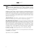
MICROTEL CellStat TM INTRODUCTION hank you for choosing the Microtel CellStatTM Dialer to implement your remote alarm monitoring solution. You have chosen a product that is simple to set up and easy to use. CellStatTM has been designed and manufactured to operate with minimal operator intervention. T The Microtel CellStatTM features a single level, interactive command structure--there are no multi-level menu structures to navigate.
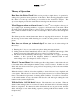
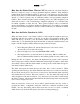
MICROTEL CellStat TM 11 2 12 10 9 1 8 6 7 5 3 4 Figure 1: Controls and Indicators 3
MICROTEL CellStat TM CHAPTER 1 - Description of the CellStatTM Dialer he CellStatTM is a small, rugged, and simple, but powerful, device which easily handles complex dialing notification and alarm monitoring. To accomplish these tasks, CellStatTM has an equally simple operator interface. Figure 1 illustrates the controls and indicators of the dialer, and the following paragraphs describe them.
MICROTEL CellStat TM (10) CELLULAR STATUS LED indicates cellular signal strength or call in-progress: BLINK (Rapid) = Cellular initialization in progress 1 BLINK (Very brief) = Cellular signal strength unknown or not detectable 1 BLINK (Long) = Weak cellular signal strength 2-3 BLINK = Normal cellular signal strength 3-5 BLINK = Strong cellular signal strength ON STEADY = Cellular call in progress The Cellular Status indication LED will repeat its pattern after 5 seconds of OFF time.
MICROTEL CellStat TM Theory of Operation How Does the Dialer Work? This section provides a simple theory of operation by asking a few questions about typical use of the dialer. The following paragraphs assume the dialer is hooked up and running as described in the Installation chapter. The Operation chapter provides the details that are missing from the discussion below.
MICROTEL CellStat TM How does the Dialer Know Who to Call? The dialer has a System Telephone Directory composed of up to 8 user-programmed telephone numbers. Each telephone number in the System Telephone Directory can be up to 30 digits long, and can specify tha the call is placed over the hardwired telephone line or via the built-in cellular module. Special ‘*’ control sequences may be embedded within a user-programmed telephone number.
MICROTEL CellStat TM If an incorrect or no access code is entered during a timed access code entry time (10 seconds), the dialer will disconnect and initialize the system Call Spacing delay timer. If the alarm condition(s) were acknowledged, then the snooze timer(s) associated with the reported alarm condition(s) will be initialized with a value equal to the programmed system Snooze Delay.
MICROTEL CellStat TM CHAPTER 2 - Installation I nstallation of the CellStatTM involves several, simple steps. This chapter outlines the physical connections to the dialer. At the end of this chapter is a Quick Start procedure which summarizes the configuration procedure of the dialer. Step One - Connect the Power Supply Connect the supplied external transformer to the 12 VDC terminals as shown in Figure 2 below. Plug the transformer into a MicroMax Surge Suppressor (Recommended by Microtel). Figure 2.
MICROTEL CellStat TM Step Two - Telephone Connections (Optional) include the external phone line for call-outs and the optional local telephone connection for local programming and monitoring. If only the built-in cellular interface is to be used, then no telephone connections are necessary. CAUTION: This equipment cannot report an alarm when other equipment (telephone, answering system, computer modem, etc.) connected to the same phone line is in use. 1.
MICROTEL CellStat TM Step Four - Connect External Input/Output to the Dialer Each Fault input has a corresponding terminal (1 - 4), and there are two COM terminals. See Figure 4 below. The terminals are large enough to accept two 14 AWG wires, so if more than two faults are wired, the COM terminals must be shared. The fault sensing circuitry is transformer and optically isolated from the dialer circuitry, but all faults share the same COM.
MICROTEL CellStat TM Quick Start Procedure This procedure outlines the steps to get the CellStatTM dialer operating in a typical manner with a minimum of programming. 1. Plug the touch-tone telephone into the Dialer PHONE jack. 2. Connect external 12 VDC transformer to dialer power supply terminal block. NOTE: External power is required in order to configure the dialer from a local phone. 3. Verify that the AC POWER/CHARGING LED illuminates (green). 4. Turn ON the dialer switch.
MICROTEL CellStat TM Individual Channel Alarm Messages: z Enter **c1 to record an alarm message for a specific I/O channel. (c = 1 to 4 for the I/O channel of interest). The dialer will respond “Ready”. z Speak your message clearly into the handset. z The dialer will speak back the message after the 6-second recording interval z Repeat procedure for the next I/O channel and message. 9. Verify Configuration Data is saved in the Dialer.
MICROTEL CellStat TM CHAPTER 3 - Operation T his chapter, divided into Configuration and Operation sections, will explain how to configure the CellStatTM to react to I/O events and how an operator can make the dialer respond to remote commands. The Microtel CellStatTM features a single level, interactive command structure--there are no multi-level menu structures to navigate.
MICROTEL CellStat TM Configuration The configuration commands described in this section modify basic dialer operation and store information about the dialer’s operational behavior in nonvolatile memory. You should only have to configure your dialer once -- all changes are saved permanently, even if AC and battery power are removed from your dialer.
MICROTEL CellStat TM z Answer Delay The number of rings the dialer will see before answering an incoming call on the telephone line. *02 **02nn Review answer delay Program answer delay Example- Command: Response: **0205 The telephone answer delay is zero five rings. z Access Code This 2 digit access code is required to access configuration commands during a telephone call to or from the dialer. *03 **03nn Review value of access code Program access code NOTE: The factory set default code is ‘12’.
MICROTEL CellStat TM Configuring Fault Inputs The CellStatTM features true modularity—Fault input channels operate completely independently of each other. Using the following commands, each Fault Input in your dialer can be configured to operate uniquely to satisfy your application requirements. For each Fault Input, record a voice message, program an alarm integration delay, and define the input channel’s normal (non-alarm) state. z I/O Channel Voice Name An individual I/O channel’s spoken voice name.
MICROTEL CellStat NOTE: Example NOTE: TM If C=5, the Power Fault channel, the response is: Command: **531 Response: Power fault channel is READY Command: **530 Response: Power fault channel is OFF When channel 5 is configured OFF it will not call out when a power failure occurs Telephone Numbers As described in the theory of operation in Chapter 1, CellStatTM can store up to eight (8) phone numbers in the System Telephone Directory.
MICROTEL CellStat TM Alarm Acknowledgment When CellStatTM calls you, you may wish to respond to the call differently depending on what type of alarm has occurred, who is on duty, the time of day, severity of the alarm, etc. If you wish the dialer to go to the next phone number on its calling list, hang up the phone. The dialer will continue on after the call spacing delay to the next phone number on the list until it receives an acknowledgment or the unlatched alarm goes away by itself.
MICROTEL CellStat TM CHAPTER 4 - Maintenance/Troubleshooting he CellStatTM Dialer is built to require minimal maintenance. Only the system battery requires your attention from time to time for your dialer to continue performing with no problems. T INTERNAL RECHARGEABLE BATTERY: A battery in typical standby use will last approximately 2 to 4 years. Battery life is mostly dependent upon the number of power outages sustained, the age of the battery, and temperature.
MICROTEL CellStat TM In addition to minutes being depleted from your dialer’s prepaid cellular account due to the dialer’s usage of the cellular account, minutes also expire after fixed time periods. The dialer is commissioned with $100 of prepaid cellular minutes at the factory; this initial account expires after one year.
MICROTEL CellStat TM Troubleshooting Guide Symptom: Cause: Cause: Cause: Cause Symptom: Cause: Cause: Cause: Cause: Cause: Cause: Unable to program with local telephone. External 12 VDC power required. (Green AC power/charging LED must be on) Incorrect command format (all commands begin with * or **). To clear out the message buffer at any time, press the ‘#’ key. Touch-tone phone must be used (listen for tones when keys are pressed).
MICROTEL CellStat TM cover and turning clockwise to increase loudness, counter-clockwise to decrease. CHAPTER 5 - Advanced Topics T his chapter details more advanced topics concerning the setup, configuration, and operation of the CellStatTM dialer. Advanced Configuration Options z Call Progress Decoding Features CellStatTM has very powerful call progress decoding features which allow great flexibility in making phone calls to pagers, answering machines, voice mail, or regular or cellular telephones.
MICROTEL CellStat Example 2- Program phone number 4 | Call using the built-in cellular communications | | | | Command Response: 24 TM | | | | | | | **64 *7 Dial phone number 5551212 | Terminate | | | | 5551212 ** Telephone number four is STAR seven five five five one two one two
MICROTEL CellStat TM APPENDICES APPENDIX A: Technical Specifications A.1 Communications A.2 Phone Interface: ACTA ID: US: 7AAAD00BDS65616 For connection to PSTN Ringer Equivalence Number: 0.0B Cellular Interface: Enabled with installation of a GSM SIM card and External antenna (usually done at factory); frontpanel cellular status indication and volume control.
MICROTEL CellStat TM AC Power/Battery Charging Indicator Resettable Internal Fuse Optional: Micromax Surge Suppressor Battery Operational: Built-in, Rechargeable 6-AA cells NiCad Battery Pack (provides 8 – 12 hours of backup power) A.4 Environmental Temperature: 20°F to 130°F operating 0°F to 130°F storage Humidity: 0-95% RH, Noncondensing EMI/RFI: Meets FCC Part 15 Class A requirements for radiated and conducted emissions A.5 Enclosure Options: Panel Mount Chassis (7.7" wide 8.
MICROTEL CellStat TM A.7 Fault Inputs Type: Isolated Dry Contact, Normal Open or Normal Closed, Non-Latched. Sensing frequency: 1 Hz Sensing current: Closed circuit sees a 10 mA (nominal), 10 millisecond-duration pulse, once every second. Sensing voltage: Open circuit sees 5 Volts (nominal) Max. Loop Resistance: 10 killiohms Max. Loop Capacitance: 100,000 picofarads Isolation: 1500 Volts, transformer and optical isolation.
MICROTEL CellStat APPENDIX B: 28 TM Glossary of Dialer Terminology Acknowledge Stops the dialer from placing additional calls concerning an alarm condition. Acknowledgment can be made by entering the '*' during alarm playback, with call-back acknowledge, or by an auto acknowledge phone escape sequence (*4) embedded within the telephone number. Alarm condition An event detected by the dialer usually causing a phone call.
MICROTEL CellStat APPENDIX C: TM FCC Requirements This equipment complies with Part 68 of the FCC rules and the requirements adopted by the ACTA. On the side of the CellStatTM metal case is a label that contains, among other information, a product identifier in the format US:AAAEQ##TXXXX. If requested, this information must be provided to the telephone company.
MICROTEL CellStat TM APPENDIX D: CellStatTM Command Summary *00 *01 *02 *03 *04 *05 *c1 *c2 *c3 **01~ **02nn **03nn **04HH **c1~ **c2SS **c31/0 *6n **6np** Report system status Voice system name (10 seconds) Answer Delay (00 – 99 rings) Access Code (00 = Disabled) Snooze Delay (HH = 00 – 99 Hours) Recites vocabulary&firmware version Fault c voice name Fault c delay (00 – 99 Seconds) Fault c alarm configuration Telephone n (n = 1 to 8) Phone Number Escape Codes *0 Tone dial (default) *1 Pulse dial *2
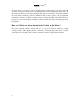
MICROTEL CellStat TM Figure 5 Mounting Dimensions 31