MICROTEL D51T Microtel D51T Operating Manual 08 March 2010 Rev. A Proprietary Notice: This document and the subject matter hereto are the property of MICROTEL, Inc. and shall not be reproduced or copied or used for the purpose of manufacturing or sale of apparatus, except by written permission of MICROTEL. MICROTEL 11725 Sunbelt Court Suite C Baton Rouge, LA 70809 225-303-0436 Fax: 225-303-0568 www.microtel-inc.
MICROTEL D51T Record of Changes Rev. A ii Date 9/14/ 09 3/8/10 Description of Changes Original Release External Temperature Firmware 1.
MICROTEL D51T TABLE OF CONTENTS INTRODUCTION 2 CHAPTER 1 - DESCRIPTION OF THE D51T DIALER 4 CHAPTER 2 - INSTALLATION 8 Quick Start Procedure CHAPTER 3 - OPERATION 11 13 Configuration Basic System Information Configuring Fault Inputs Telephone Numbers 14 14 16 18 Operations Alarm Acknowledgment Checking System Status Controlling the local output relay 18 19 19 20 CHAPTER 4 - MAINTENANCE/TROUBLESHOOTING 21 CHAPTER 5 - ADVANCED TOPICS 23 Advanced Configuration Options APPENDICES 23 2
MICROTEL D51T INTRODUCTION T hank you for choosing the Microtel D51T Dialer to implement your remote digital and temperature alarm monitoring solution. You have chosen a product that is simple to set up and easy to use. D51T has been designed and manufactured to operate with minimal operator intervention. The Microtel D51T features a single level, interactive command structure--there are no multi-level menu structures to navigate.
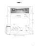
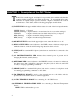
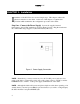
MICROTEL D51T Figure 1: Controls and Indicators 3
MICROTEL D51T CHAPTER 1 - Description of the D51T Dialer T he D51T is a small, rugged, and simple, but powerful, device which easily handles complex dialing notification and alarm monitoring. To accomplish these tasks, D51T has an equally simple operator interface. Figure 1 illustrates the controls and indicators of the dialer, and the following paragraphs describe them.
MICROTEL D51T How Does the Dialer Work? This section provides a simple theory of operation by asking a few questions about typical use of the dialer. The following paragraphs assume the dialer is hooked up and running as described in the Installation chapter. The Operation chapter provides the details that are missing from the discussion below. What Happens when an Alarm Occurs? D51T has a telephone directory of up to four people, answering machines, or pagers to call in the event of an alarm.
MICROTEL D51T These include tone/pulse selection dialing, pauses, auto acknowledgment of an alarm call-out, dial '*' or '#' for interfacing to telephone equipment. These special sequences allow a tremendous amount of flexibility on a telephone number by number basis. How does the Dialer Prioritize its Calls? When the dialer detects a new alarm condition, it will search the telephone directory, beginning with the first number on the list, for the first valid telephone number.
MICROTEL D51T How can I Make an Alarm Sound in the Vicinity of the Dialer? The local summary alarm contacts will be de-energized (opened) whenever a fault condition exists. This output could be connected to an interposing relay whose contacts would be used to switch a siren or bell to warn the local area of the alarm condition.
MICROTEL D51T CHAPTER 2 - Installation I nstallation of the D51T involves several, simple steps. This chapter outlines the physical connections to the dialer. At the end of this chapter is a Quick Start procedure which summarizes the configuration procedure of the dialer. Step One - Connect the Power Supply Connect the supplied external transformer to the 12 VDC terminals as shown in Figure 2 below. Plug the transformer into a MicroMax Surge Suppressor (Recommended by Microtel). Figure 2.
MICROTEL D51T Step Two - Telephone Connections include the external phone line for call-outs and the optional local telephone connection for local programming and monitoring. CAUTION: This equipment cannot report an alarm when other equipment (telephone, answering system, computer modem, etc.) connected to the same phone line is in use. 1. Connect the dialer’s LINE jack to the EQUIPMENT Phone jack of the MicroMax Surge Suppressor using the cable supplied with your dialer. 2.
MICROTEL D51T below. The terminals are large enough to accept two 14 AWG wires, so if more than two faults are wired, the COM terminals must be shared. The fault sensing circuitry is transformer and optically isolated from the dialer circuitry, but all faults share the same COM. Use 22 AWG shielded twisted pair wire when wiring external sensors to the I/O terminals. Whenever possible, ground the shield at the sensor end only. Sensor control wires should never share conduit with AC power wiring.
MICROTEL D51T Quick Start Procedure This procedure outlines the steps to get the D51T dialer operating in a typical manner with a minimum of programming. 1. Plug the touch-tone telephone into the Dialer PHONE jack. 2. Connect external 12 VDC transformer to dialer power supply terminal block. NOTE: External power is required in order to configure the dialer from a local phone. 3. Verify that the AC POWER/CHARGING LED illuminates (green). 4. Turn ON the dialer switch. Take the telephone off-hook.
MICROTEL D51T Individual Channel Alarm Messages: Enter **c1 to record an alarm message for a specific I/O channel. (c = 1 to 4 for the I/O channel of interest). The dialer will respond “Ready”. Speak your message clearly into the handset. The dialer will speak back the message after the 6-second recording interval Repeat procedure for the next I/O channel and message. 9. Verify Configuration Data is saved in the Dialer. Turn OFF the Dialer’s power switch, wait a few seconds, then turn it ON again.
MICROTEL D51T CHAPTER 3 - Operation T his chapter, divided into Configuration and Operation sections, will explain how to configure the D51T to react to I/O events and how an operator can make the dialer respond to remote commands. The Microtel D51T features a single level, interactive command structure--there are no multi-level menu structures to navigate.
MICROTEL D51T Configuration The configuration commands described in this section modify basic dialer operation and store information about the dialer’s operational behavior in nonvolatile memory. You should only have to configure your dialer once -- all changes are saved permanently, even if AC and battery power are removed from your dialer.
MICROTEL D51T Answer Delay The number of rings the dialer will see before answering an incoming call. *02 **02nn Review answer delay Program answer delay Example- Command: Response: **0205 The answer delay is zero five. Access Code This 2 digit access code is required to access configuration commands during a telephone call to or from the dialer. *03 **03nn Review value of access code Program access code NOTE: The factory set default code is ‘12’.
MICROTEL D51T Configuring Fault Inputs The D51T features true modularity—Fault input channels operate completely independently of each other. Using the following commands, each Fault Input in your dialer can be configured to operate uniquely to satisfy your application requirements. For each Fault Input, record a voice message, program an alarm integration delay, define the input channel’s normal (non-alarm) state, and configure whether cleared alarms should be reported.
MICROTEL D51T Example- Command: Response: **430 Channel four normal state is closed NOTE: Example If C=5, the Power Fault channel, the response is: Command: **531 Response: Power fault channel is ENABLED Command: **530 Response: Power fault channel is DISABLED NOTE: When channel 5 is configured OFF it will not call out when a power failure occurs.
MICROTEL D51T NOTE: The Low and High Temperature Alarms must be ENABLED using the **c31/0 I/O Alarm Configuration command defined above. *c5 **c5nnn Review I/O channel c Alarm Setpoint Program I/O channel c Alarm Setpoint Example- Command: Response: Example- Command: Response: ** 6 5 039 The low temperature alarm point is three nine degrees. ** 7 5 090 The high temperature alarm point is nine zero degrees.
MICROTEL D51T This section details operation of the dialer, from both local and remote locations. Sections will detail the following actions: Alarm Acknowledgment Checking System Status Controlling the local output relay Alarm Acknowledgment When D51T calls you, you may wish to respond to the call differently depending on what type of alarm has occurred, who is on duty, the time of day, severity of the alarm, etc.
MICROTEL D51T *00 Report system status Example- Command: Response: *00 Channel one normally closed digital input in alarm. Temperature is seven eight degrees. The local output is open. Controlling the local output relay D51T has a set of output contacts that may be controlled from a touch-tone phone. These contacts may be used to turn ON or OFF external equipment, or as a signal input to another device.
MICROTEL D51T CHAPTER 4 - Maintenance/Troubleshooting T he D51T Dialer is built to require minimal maintenance. Only the system battery requires your attention from time to time for your dialer to continue performing with no problems. INTERNAL RECHARGEABLE BATTERY: A battery in typical standby use will last approximately 2 to 4 years. Battery life is mostly dependent upon the number of power outages sustained and the age of the battery, and temperature.
MICROTEL D51T TROUBLESHOOTING: Symptom: Cause: Cause: Cause: Cause Symptom: Cause: Cause: Cause: Cause: Cause: Cause: 22 Unable to place telephone calls (Line LED comes on but no ring at called telephone number). Phone number not entered correctly. Call being placed to different number than expected. Phone line not plugged-in, phone line broken or in use. No touch-tone service,use pulse method by pre-pending *1 to each phone number Unable to program with local telephone. External 12 VDC power required.
MICROTEL D51T CHAPTER 5 - Advanced Topics T his chapter details more advanced topics concerning the setup, configuration, and operation of the D51T dialer. Advanced Configuration Options Call Progress Decoding Features D51T has very powerful call progress decoding features which allow great flexibility in making phone calls to pagers, answering machines, voice mail, or regular or cellular telephones.
MICROTEL D51T Example 2- Command Response: Program phone number 8 | Pulse dial the following digits | | | **88 | | | *1 Dial phone number 5551212 | Terminate | | 5551212 ** Telephone number eight is STAR one five five five one two one two Reduced power operation D51T’s already low power consumption can be reduced 33% for installations providing minimal power, such as solar panels.
MICROTEL D51T APPENDICES APPENDIX A: Technical Specifications A.1 Communications A.2 Phone Interface: ACTA ID: 7AAAD00BDS65616 For connection to PSTN or Cellular network via Cellular Interface. Ringer Equivalence Number: 0.
MICROTEL D51T A.3 Environmental Temperature: 20°F to 122°F operating 0°F to 130°F storage Humidity: 0-95% RH, Noncondensing EMI/RFI: Per FCC Part 15 Class A A.4 Enclosure Options: Panel Mount Chassis (7.7" wide 8.8" high x 4" deep) Suitable for Wall or Panel Mounting Battery Mounted Separately Nema 4 Fiberglass Case with Hard Cover (12” Wide, 15.5” High, 6.6” Deep) Nema 12 Fiberglass Case with Hard Cover Nema 12 Fiberglass Case with Clear Cover (9” Wide, 10.5”High, 6.
MICROTEL D51T Sensing voltage: Open circuit sees 5 Volts (nominal) Max. Loop Resistance: 10 killiohms Max. Loop Capacitance: 100,000 picofarads Isolation: 1500 Volts, transformer and optical isolation. Fault Integration Delay: 00 – 99 seconds AC Power Fail Detect: Internal circuit, configurable enable and alarm delay A.7 Temperature Measurement and Alarms Type: Accuracy: Reporting Resolution: Low Temperature Alarm: High Temperature Alarm: Onboard, internal to the enclosure, temperature IC.
MICROTEL D51T APPENDIX B: Glossary of Dialer Terminology Acknowledge Stops the dialer from placing additional calls concerning an alarm condition. Acknowledgment can be made by entering the '*' during alarm playback, with call-back acknowledge, or by an auto acknowledge phone escape sequence (*4) embedded within the telephone number. Alarm condition An event detected by the dialer usually causing a phone call.
MICROTEL D51T APPENDIX C: FCC Requirements This equipment complies with Part 68 of the FCC rules and the requirements adopted by the ACTA. On the side of the D51T metal case is a label that contains, among other information, a product identifier in the format US:AAAEQ##TXXXX. If requested, this information must be provided to the telephone company.
MICROTEL D51T APPENDIX D: D51T Command Summary *00 *01 *02 *03 *04 *05 *06 *c1 *c2 *c3 *c4 *c5 **01~ **02nn **03nn **04HH **060/1/2 **c1~ **c2SS **c30/1/2 **c40/1 **c5nnn *8n **8np** Report system status Voice system name (10 seconds) Answer Delay (00 – 99 rings) Access Code (00 = Disabled) Snooze Delay (HH = 00 – 99 Hours) Recites vocabulary&firmware version Control local output Fault Fault Fault Fault Fault c c c c c voice name delay (00 – 99 Seconds) alarm configuration Return-To-Normal config Alar
MICROTEL D51T APPENDIX E: Mechanical Dimensions Figure 4 Mounting Dimensions 31