
System Manual


26-0002-0003/5 (en) (2021) 5
LIST OF FIGURES
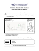
Figure 1.1: (A) Device Placement, (B) In-office Set-up ....................................................................... 7
Figure 2.1: SAPS Hardware Set-up Overview .................................................................................. 10
Figure 2.2: Application Warning Screen ........................................................................................... 11
Figure 2.3: Startup Menu Screen—Welcome Menu ......................................................................... 12
Figure 2.4: WT Interface “Connected” Indicator ................................................................................ 12
Figure 3.1: Log In ............................................................................................................................. 13
Figure 3.2: Startup Menu Screen—Physician Mode ......................................................................... 14
Figure 3.3: Buttons Versus Tabs ...................................................................................................... 14
Figure 3.4: Blue Text Indicates Settings Have Not Been Saved ....................................................... 15
Figure 4.1: Program Implant ............................................................................................................. 17
Figure 4.2: Disconnect ..................................................................................................................... 17
Figure 4.3: Blank Serial # ................................................................................................................. 17
Figure 4.4: Interrogate Button on Screen ......................................................................................... 18
Figure 4.5: Interrogate ...................................................................................................................... 18
Figure 4.6: Select Button .................................................................................................................. 18
Figure 4.7: Serial # and Battery Status ............................................................................................. 19
Figure 4.8: Time Button .................................................................................................................... 19
Figure 4.9: Time 19
Figure 4.10: Patient ID ..................................................................................................................... 20
Figure 4.11: Implant Setting Parameters .......................................................................................... 21
Figure 4.12: Amplitude ..................................................................................................................... 21
Figure 4.13: Frequency .................................................................................................................... 22
Figure 4.14: Train Duration .............................................................................................................. 22
Figure 4.15: Pulse Width .................................................................................................................. 23
Figure 4.16: Stim Test Mode ............................................................................................................ 24
Figure 4.17: Implant Settings............................................................................................................ 24
Figure 4.18: Therapist Trigger Mode ................................................................................................ 25
Figure 4.19: Implant Settings............................................................................................................ 26
Figure 4.20: Lead Impedance Check ................................................................................................ 27
Figure 4.21: High Lead Impedance Notification ................................................................................ 27
Figure 4.22: Low Lead Impedance Notification ................................................................................. 28
Figure 4.23: Lead Impedance Displayed .......................................................................................... 28
Figure 5.1: On-Demand Mode .......................................................................................................... 29
Figure 5.2: Start / Stop On-Demand Magnet Trigger ........................................................................ 30
Figure 5.3: On-Demand Mode Therapy via the VNS Pairing Therapy Menu ..................................... 31
Figure 5.4: Select Task .................................................................................................................... 32
Figure 5.5: Start Task ....................................................................................................................... 33
Figure 5.6: Communication Established and Ready to Stimulate ..................................................... 33
Figure 5.7: Stimulate Selected—Status “Stimulating” ....................................................................... 34
Figure 5.8: Status “Refractory”—No Stimulation Allowed ................................................................. 34
Figure 5.9: Stimulation Counter ........................................................................................................ 34