
Specifications


MDS 05-3447A01, Rev. F MDS 1710A/C and MDS 2710A/C/D 9
Invisible place holder
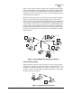
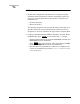
Figure 5. Typical Remote Station Arrangement
3.1 Installation Steps
Below are the basic steps for installing the transceiver. In most cases,
these steps alone are sufficient to complete the installation. More
detailed explanations appear at the end of these steps.
1. Mount the transceiver to a stable surface using the brackets supplied
with the radio.
2. Install the antenna and antenna feedline for the station. Preset direc-
tional antennas in the desired direction.
3. Connect the data equipment to the transceiver’s
DATA INTERFACE
connector. Use only the required pins for the application—Do not
use a fully pinned (25 conductor) cable. Basic applications may
require only the use of Pin 2 (transmit data—TXD), Pin 3 (Received
Data—RXD) and Pin 7 (signal ground). The radio can be keyed
with the use of the
DATAKEY command.
Additional connections may be required for some installations.
Refer to the complete list of pin functions provided in Table 4 on
page 14.
4. Measure and install the primary power for the radio. The red wire on
the power cable is the positive lead; the black is negative.
13.8 VDC
POWER
CABLE
13.8 VDC
2.5 A (Minimum)
POWER SUPPLY
REMOTE TERMINAL
UNIT
ANTENNA SYSTEM
LOW-LOSS FEEDLINE
RADIO
TRANSCEIVER