
Specifications

MDS 05-3447A01, Rev. F MDS 1710A/C and MDS 2710A/C/D 15
Invisible place holder
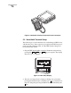
4.0 OPERATION
In-service operation of the transceiver is completely automatic. Once
the unit has been properly installed and configured, operator actions are
limited to observing the front panel LED status indicators for proper
operation.
If all parameters are correctly set, operation of the radio can be started
by following these steps:
1. Apply DC power to the transceiver.
2. Observe the LED status panel for the proper indications (Table 5).
3. If not done earlier, refine the antenna heading of the station to maxi-
mize the received signal strength (RSSI) from the master station.
Use the
RSSI command from an HHT connected to the radio’s DIAG.
connector.—See Section 5.0, TRANSCEIVER PROGRAMMING.
This can also be done with a DC voltmeter as described in
Section 4.2, RSSI Measurement.
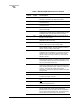
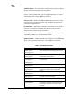
19 OUT 9.9 Vdc Regulated Output. Provides a source of
regulated voltage at 100 mA for low power accessories.
20 -- Do not connect—Reserved for future use.
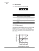
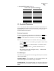
21 OUT RSSI—Received Signal Strength Indication. A DC
voltmeter may be connected to this pin to read the relative
strength of the incoming signal. Figure 8 is a chart showing
RSSI vs. DC voltage.
22 -- Do not connect—Reserved for future use.
23 IN Diagnostic Channel Enable. A ground on this pin causes
the radio’s microcontroller to open the DB-25 DATA
INTERFACE for diagnostics and control instead of the
normal RJ-11 DIAG. connection.
24 -- Do not connect—Reserved for future use.
25 OUT Alarm. A logic low (less than 0.5 volts) on this pin indicates
normal operation. A logic high (greater than 4 volts)
indicates that some alarm condition is present. This pin
can be used as an alarm output, provided the internal
series resistance of 1 kΩ is considered.
Table 4. DATA INTERFACE Connector Pinouts (Continued)
Pin
Number
Input/
Output Pin Description