
Specifications

16 MDS 1710A/C and MDS 2710A/C/D MDS 05-3447A01, Rev. F
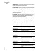
4.1 LED Indicators
Table 5 describes the function of each status LED.
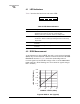
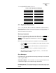
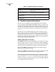
4.2 RSSI Measurement
As an alternative to using an HHT, the radio’s received signal strength
(RSSI) may be read with a DC voltmeter connected to Pin 21 of the
DATA
INTERFACE connector. Figure 8 shows the relationship between
received signal level and the DC voltage on Pin 21 of the
DATA INTER-
FACE connector. (Note: Readings are not accurate for signals stronger
than –50 dBm.)
Invisible place holder
Figure 8. RSSI vs. Vdc (Typical)
PWR DCD TXD RXD
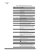
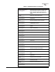
Table 5. LED Status Indicators
LED Name Description
PWR • Continuous—Power is applied to the radio, no problems detected.
• Rapid flash (five times-per-second)—Fault indication.
• Flashing once every 5 seconds—Radio is in Sleep mode.
DCD • Flashing—Indicates the radio is receiving intermittent data frames.
• Continuous—Radio is receiving a data signal from a continuously
keyed radio.
TXD An EIA-232 mark signal is being received at the DATA INTERFACE
connector.
RXD An EIA-232 mark signal is being sent out from the DATA INTERFACE
connector.
2
2.5
3
3.5
4
–110
–90
–70
–50
+ DC VOLTS (PIN 21)
SIGNAL LEVEL (dBm)
4.5
5.0