
Specifications

MDS 05-3447A01, Rev. F MDS 1710A/C and MDS 2710A/C/D 17
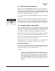
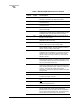
5.0 TRANSCEIVER PROGRAMMING
Programming and control of the transceiver is performed through the
radio’s RJ-11
DIAG. (Diagnostics) connector with an MDS Hand-Held
Terminal (MDS P/N 02-1501A01). This section contains a reference
chart (Table 7) followed by detailed descriptions for each user com-
mand.
NOTE: In addition to HHT control, Windows-based software is avail-
able (MDS P/N 03-3156A01) to allow diagnostics and
programming using a personal computer. An installation
booklet and on-line instructions are included with the soft-
ware. Contact MDS for ordering information.
5.1 Hand-Held Terminal Connection & Startup
This section gives basic information for connecting and using the MDS
Hand-Held Terminal. For more information about the terminal, refer
also to the instructions included with each HHT kit.
The steps below assume that the HHT has been configured for use with
the transceiver (80 character screen display). If the HHT was previously
used with a different model transceiver, or if its default settings have
been changed, refer to Section 5.2, Hand-Held Terminal Setup for setup
details.
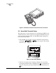
Follow these steps to connect the HHT:
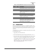
1. Connect the HHT’s coiled cord to the
DIAG. (RJ-11) jack on the
radio as shown in Figure 9. This automatically places the radio into
the control and programming mode.
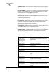
As an alternative, the
DATA INTERFACE (DB-25) connector may be
used for programming instead of the
DIAG. jack. With this arrange-
ment, Pin 23 of the HHT cable must be grounded to enable the diag-
nostic channel. (See Table 4.)
2. When the HHT is connected, it runs through a brief self-check,
ending with a beep. After the beep, press to obtain the ready
“>” prompt.
ENTER