
Specifications


36 MDS 1710A/C and MDS 2710A/C/D MDS 05-3447A01, Rev. F
3. Program all other radios in the network as nodes by entering the
DTYPE NODE command at each radio.
4. Use the
DLINK ON and DLINK [baud rate] commands to configure the
diagnostic link protocol on the RJ-11 port of each node radio.
5. Connect same-site radios using a null-modem cable at the radios’
diagnostic ports.
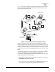
6. Connect a PC on which MDS InSite software is installed to the root
radio, or to one of the nodes, at the radio’s diagnostic port. (This PC
may be the PC being used to collect payload data, as shown in
Figure 12.)
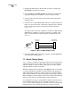
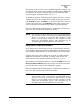
To connect a PC to the radio’s
DIAG. port, an RJ-11 to DB-9 adapter
(MDS P/N 03-3246A01) is required. If desired, an adapter cable
may be constructed from scratch using the information shown in
Figure 13.
Invisible place holder
Figure 13. RJ-11 to DB-9 Adapter Cable
7. Launch the MDS InSite application at the PC. (See the MDS InSite
User’s Guide for instructions.)
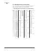
7.3 Bench Testing Setup
Figure 14 shows a sample test setup that can be used to verify the basic
operation of transceivers in a shop setting. The test can be performed
with any number of remote radios by using a power divider with the
required number of output connections.
The RTU simulator shown in the test setup (MDS Part No. 03-2512A01)
is a microcontroller that emulates a remote terminal unit operating at
1200, 2400, 4800, or 9600 bps. Custom software is supplied with the
RTU simulator that allows continuous polling of remote radios using an
IBM-compatible personal computer. The software reports the number of
polls sent, polls received, and the number of errors detected.
As an alternative to using an external RTU simulator, the transceiver’s
internal RTU simulator may be used (see
RTU command in Table 7 on
page 20). (This will not provide as conclusive a test as an external sim-
ulator because it does not utilize the transceiver’s data connector.)
RXD
TXD
GND
2
3
5
DB-9 FEMALE
(TO COMPUTER)
TXD
RXD
GND
4
5
6
RJ-11 PLUG
(TO RADIO)
RJ-11 PIN LAYOUT
1
6