
User Manual Part 2


Advanced Operations 5-30MTX5000 User and Technical Manual
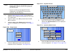
104. Select the Main option button and observe the Main
screen is displayed.
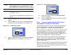
5.4.3 Create or Update Digital ASI Preset
Configuration Settings in Local Mode
The procedure required to create a new custom digital ASI
Preset configuration or to update an existing digital ASI Preset
configuration is contained in the following steps.
When preparing a new digital ASI Preset, you must first select an
existing digital ASI Preset from either the ASI factory default
Preset or from your own custom digital ASI Presets. The
selected digital ASI Preset will be used as a “make-from” to
prepare the new digital ASI Preset configuration.
Please note that while the ASI factory default Preset may be
used to prepare a new Preset configuration, the factory default
Preset cannot be changed or deleted. It can only be used as
a “make-from”.
When the new configuration is prepared using the factory default
Preset, it cannot be saved with the factory Preset number or
Preset name. A new Preset number and Preset name must be
assigned to the new Preset.
When using a custom Preset as a “make-from”, the new Preset
should be saved with a new Preset number. When you save the
new Preset, the Preset number will automatically be increased to
the next available Preset number. If you select an existing
Preset number when saving the new Preset, the original custom
Preset will be overwritten and cannot be recovered. The only
way to restore a Preset that has been overwritten is to re-enter
the custom Preset data from scratch.
If you are updating configuration settings on an existing custom
Preset, when you save the configuration settings, the Preset
number will automatically be increased to the next available
Preset number. You must enter and save the configuration
settings using the original Preset number.
Note
In the following steps, the color LCD display option
buttons and pull-down menu options may be
selected using either the touch screen or the
function keys and the SEL key.
1. Verify the MTX5000 IDU is powered up. See
”Powering the MTX5000 System” on page 3-7.
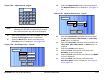
2. Observe the Main screen is displayed. See Figure 5-
67.
Figure 5-67: Main Screen - Typical
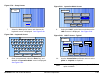
3. Select the L/R option button for L (local mode), as
required.
Channel 1 0Offset
Antenna Ant. Pol.Antenna1 H
RFU1
No RF
RF Band
Preset A
Analog
4.83 & 5.8, 3MHz Vid Dev
RF Output
XX
dBm
<- Status
Setup
Status ->
PA Off
SUM
ODU
IDU
RF
L/R
L
L
PA
Operation
Button