
User Guide
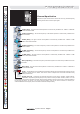
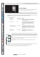
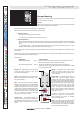
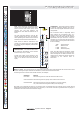
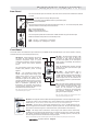
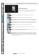
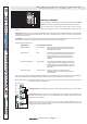
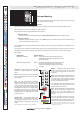
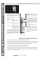
Table Of Contents
line L
PUSH
insert
mic
line
in
direct
out
(stereo only)
line in left
line in right
51
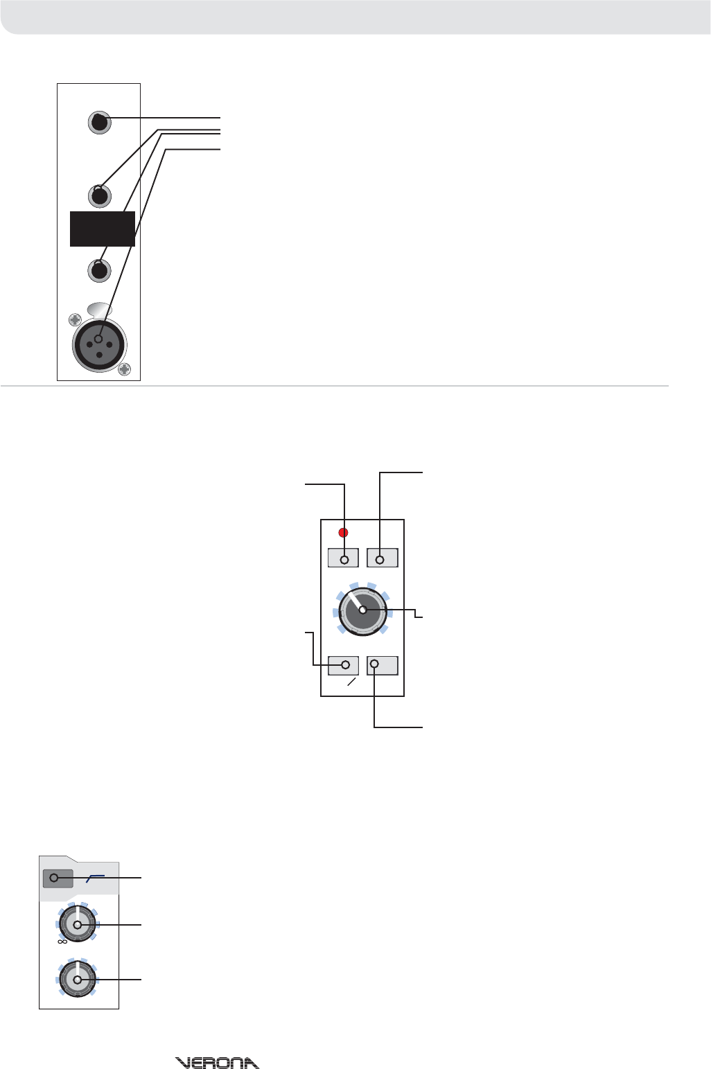
Hi-Pass
Line Gain
Image
- The high pass switch enables an 80Hz high pass filter on the microphone input. This
is commonly used to remove handling noise, bass rumble through coupling with the stage or
mains hum.
- The line gain is continuously variable from off (-inf) to +20dB allowing for low
level line signals to be trimmed to obtain the optimal signal level. The pre-fade input signal
level can be monitored using the in-channel LED meter (discussed later in this section).
- The image control controls the stereo image of the channel and is continuously
variable from mono through Left-Right stereo to a wide stereo image. The wide stereo image
uses phase cancellation techniques to create a ‘wider’ sounding signal by removing an
amount of signal common to both the left and right signals.
Note: On stereo channels, the channel HPF has no effect upon the left and right line inputs.
Note: The Line and MIC inputs are summed together and can be used simultaneously sharing the channel controls.
Front Panel
The actual number of multifunction input channels on your Midas Verona will depend upon your choice of frame. However,
each frame functions in essentially the same way.
mic gain
+30 +45
+60+15
mic
padpower
48v -15
O
ins
mono
wide
stereo
image
line gain
hi-pass
80Hz
+20
0
Multi Function Input ChannelsMulti Function Input Channels
The Verona channel inputs are located on the rear of the console. Each multifunction channel
provides:
one insert point on a single TRS jack socket;
The insert point operates on the XLR microphone input only (i.e. not on the line inputs) and is
unbalanced and conventionally
two quarter-inch TRS balanced line in jack socket inputs;
one mic XLR female.
wired insert where:
- Channel Signal Send
- Channel Signal Return
- Signal Common Ground
The insert points operate at a nominal level of 0dBu and acts only upon the MIC input.
Balanced XLR and Jack inputs are conventionally wired:
- 1. Screen - 2. Hot Signal - 3. Cold Signal
- T. Hot Signal - R. Cold Signal - S. Screen
Tip
Ring
Sleeve
XLR
TRS
Operators Manual - Page 14
Rear Panel
48v Power
Mic Ø
- When depressed, the Verona
will apply 48 volts phantom power the
channel’s microphone input to power
condenser microphones, direct inject boxes
or other devices that require phantom
power.
The red phantom power LED will light to
indicate that phantom power is being
applied.
- The microphone phase switch
causes a 180 degree phase change (with
respect to the input) to occur in the input
amplifier inverting the phase of the
microphone signal to the channel. This is
generally desirable when trying to sum two
signals that are out of phase which would
lead to cancellation (especially at low
frequencies). For example, when trying to
use microphone signals from both the top
and bottom head of a snare drum.
Note: On stereo channels, the phase switch has no effect
upon the left and right line inputs.
Mic Pad
Mic Gain
Ins
- The Pad switch provides 15dB
attenuation on the input to allow the
connection of high output microphones
and line level signals (to the microphone
input) without overloading the channel’s
input amplifier.
Note: On multifunction channels, the Pad
switch has no effect upon the left & right
line level inputs.
- The microphone gain is
continuously variable from +15dB to
+60dB (effective channel input gain 0dB to
+45dB with pad enabled). The pre-fade
channel input level can be monitored on
the in-channel LED meter (discussed later
in this section).
- The insert switch enables the channel
insert point by connecting the insert return
to the channel signal signal path. This
allows for the insertion of dynamic
processors or effects into the signal path
(for example, compression, limiting or
gating of microphone signals).
Note: On stereo channels, the channel insert has no
effect upon the left and right line inputs.