
Operation Manual


DSP modules 11
DL371 Audio System Engine
Operator Manual
DSP modules
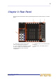
Seven module slots in the rear panel each accept the following module. However, in
the standard PRO6 configuration, only five modules are fitted to the DL371 Audio
System Engine.
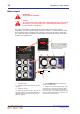
The modules are numbered as shown in the following diagram.
1 DSP audio sections 0 and 1 with two sets
of LEDs (link and data) for status indication.
2 Link ok LED (green) illuminates to
indicate that link is active (link is good).
3 Link error LED (green) illuminates to
indicate that link has failed.
4 Data ok LED (red) illuminates to indicate
valid audio and valid aux data (data is good).
5 Data error LED (red) illuminates to
indicate there is no audio.
6 DSP control section has the same
functionality as the one on the front panel (see
“DSP control panel” on page 7).
7 AES50 audio section, has the same
functionality as the AES50 audio - internal
section of the front panel (see “AES50 audio
panels” on page 7).
8 diagnostics 9-way D-type connector
socket (female). For use by service personnel
only.
8
1
6
7
2
3
4
5
1234567