M32 DIGITAL CONSOLE Digital Console for Live and Studio with 40 Input Channels, 32 MIDAS Microphone Preamplifiers and 25 Mix Buses User Manual
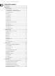
M32 DIGITAL CONSOLE User Manual Table of Contents Precautions...................................................................... 4 Introduction.................................................................... 5 1. Control Surface........................................................... 6 1.1 Channel Strip - Input Channels....................................... 6 1.2 Channel Strip - Group/Bus Channels............................ 7 1.3 Config/Preamp.................................................
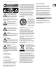
M32 DIGITAL CONSOLE User Manual Important Safety Instructions Terminals marked with this symbol carry electrical current of sufficient magnitude to constitute risk of electric shock. Use only high-quality commercially-available speaker cables with plugs pre-installed. All other installation or modification should be performed only by qualified personnel.
M32 DIGITAL CONSOLE User Manual Precautions Before installing, setting up or operating this equipment make sure you have read and fully understand all of this section and the ‘IMPORTANT SAFETY INSTRUCTIONS’ at the front of this manual. This equipment is supplied by a mains voltage that can cause electric shock injury! The following must be observed in order to maintain safety and electromagnetic compatibility (EMC) performance. Safety warnings Signal 0V is connected internally to the chassis.
M32 DIGITAL CONSOLE User Manual Audio connections To ensure the correct and reliable operation of your equipment, only high quality, balanced, screened, twisted pair audio cable should be used. XLR connector shells should be of metal construction so that they provide a screen when connected to the control centre and, where appropriate, they should have Pin 1 connected to the cable screen.
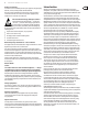
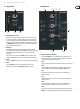
M32 DIGITAL CONSOLE User Manual 1. Control Surface 1.1 Channel Strip - Input Channels (5) (1) (6) (7) (8) (9) (2) (3) (10) (4) (1) REM - DAW Remote Button Press this button to enable remote control of your Digital Audio Workstation software using the Group/Bus fader section controls. This section can emulate HUI or Mackie Control Universal communication with your DAW.
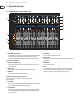
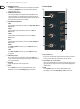
M32 DIGITAL CONSOLE User Manual 1.2 Channel Strip - Group/Bus Channels (1) (6) (7) (8) (9) (10) (11) (12) (2) (3) (5) (4) (1) FADER FLIP - SENDS ON FADER Button Press to activate the M32’s Sends on Fader function. This function aids with the level setting of channels sent to any of the 16 Mix Buses. It is only for channels assigned to Mix Buses 1-16, and does not work for DCA groups, main or matrix buses.
M32 DIGITAL CONSOLE User Manual Main (6) SEL Button Press to select the Main bus for editing. (7) COMP The COMP indicator will illuminate when compression is being applied to the stereo output mix. (9) CLR SOLO Button Press to clear all sources assigned to the solo bus. (10) SOLO Button Press to solo the main bus. (11) Scribble Strip Customisable information relating to the main bus are displayed here. (12) MUTE Button Press to mute the main bus.
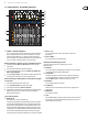
M32 DIGITAL CONSOLE User Manual 1.5 Dynamics 1.6 Equaliser (1) (1) (2) (3) (4) (7) (2) (3) (4) (1) THRESHOLD Rotary Control Dynamic Range Compression, or just Compression is a device that is used to control the volume of an audio signal. Often used in conjunction with a noise gate (see GATE), which attenuate signals below a certain threshold, compressors attenuate signals that register above the threshold.
M32 DIGITAL CONSOLE User Manual (2) WIDTH Rotary Control The WIDTH rotary control determines the span of frequencies around that specified by the FREQUENCY rotary control, which will be affected by adjusting the GAIN control. (3) FREQUENCY Rotary Control Select the specific frequency to be adjusted with the FREQUENCY rotary control. Each frequency can be adjusted between 20 Hz and 20 kHz.
M32 DIGITAL CONSOLE User Manual 1.8 Main Bus To record to a USB stick, perform the following steps: (1) (3) (2) (4) (5) (1) LEVEL Rotary Adjust the overall send level to the Mono Bus with the LEVEL rotary control. (2) PAN/BAL Rotary When the selected channel is assigned to the Stereo Bus, the PAN/BAL rotary control adjusts the left to right positioning of the audio signal. (3) MONO Press the MONO button to assign the selected channel to the Main Mono/ Centre Bus.
M32 DIGITAL CONSOLE User Manual 1.10 Main Display (Summary) (1) (2) (3) (4) (5) (1) DISPLAY SCREEN The controls in this section are used in conjunction with the colour screen in order to navigate and control the graphical elements it contains. By including dedicated push encoders that correspond to the adjacent controls on the screen, as well as including cursor buttons, the user can quickly navigate and control all of the colour screen’s elements.
M32 DIGITAL CONSOLE User Manual LIBRARY The LIBRARY screen allows loading and saving of commonly-used setups for the channel inputs, effects processors, and routing scenarios. The LIBRARY screen contains the following tabs: channel: This tab allows the user to load and save commonly used combinations of the channel processing, including dynamics and EQ. effects: This tab allows the user to load and save commonly used effects processor presets.
M32 DIGITAL CONSOLE User Manual (5) VIEW Press the VIEW button to access more detailed parameters on the Main Display. Operation The MONITOR section shares a Main Display screen with the TALKBACK section. On this screen, only the monitor tab contains functionality which relates to the MONITOR section. This tab controls various console options relating to the solo bus, as well as the console’s control room outputs.
M32 DIGITAL CONSOLE User Manual 1.12 Talkback (1) (2) (3) (4) (5) (1) EXT MIC Port Connect a microphone to the console via a standard XLR cable. The output carries 48 V phantom power, allowing the use of condenser or dynamic microphones. (2) TALK LEVEL Rotary Control Adjust the level of the Talkback volume with the TALK LEVEL rotary control. (3) / (4) TALK A / B Select the destination of the Talkback mic signal with either the TALK A or TALK B buttons.
M32 DIGITAL CONSOLE User Manual 6. Adjust the fourth encoder to select the type of oscillator to be used. Choices include: • Sine Wave • Pink Noise • White Noise. 7. Tap the fourth encoder to engage the selected oscillator type. 8. Adjust the sixth encoder to select a destination for the onboard oscillator. Choices include: • Mix Bus 1-16 • Main L Bus • Main R Bus • Main L+R Bus • Main Centre / Mono • Matrix Outputs 1-6. 9.
M32 DIGITAL CONSOLE User Manual Utility Pressing the UTILITY button to the right of the Main Display changes the bottom of the home tab to the following configuration: Utility Pressing the UTILITY button to the right of the Main Display changes the bottom of the snippets tab to the following configuration: Each of the functions on this layer can be controlled with the adjacent push encoder as follows: Copy - Allows the user to make a copy of the currently-selected Cue.
M32 DIGITAL CONSOLE User Manual Column 4: Console • Configuration • Solo • Routing • Output Patch. CHANNEL SAFE The SHOW CONTROL screen’s chan safe tab configures which console channels are and are not changed when a scene change occurs. This allows the user to protect certain channels from ever changing during a scene change, giving them as much control as possible for key audio sources.
M32 DIGITAL CONSOLE User Manual The ASSIGN screen contains the following separate tabs: home: This screen provides a general overview of the 12 assigned controls for all three control sets at the same time. set A: This screen allows assignment of different console parameters to the 12 custom controls for Set A.
M32 DIGITAL CONSOLE User Manual 4. When you have assigned all of the desired channels to the mute group, release the dedicated Mute Group button. NOTE: The individual channel MUTE buttons will remain fully functional during the assignment process, only the mute group buttons are blocked. To use the MUTE GRP screen to mute or unmute the groups, perform the following steps: 1.
M32 DIGITAL CONSOLE User Manual 6. Adjust the fourth encoder to select to which of the six mute groups the currently selected channel will be assigned. 7. Tap the fourth encoder to assign the currently selected channel to the selected mute group. 8. Tap the fifth encoder to toggle solo on/off for the currently selected channel. 9. Turn the sixth encoder to adjust the fader level for the currently selected channel. 10. Tap the sixth encoder to toggle mute on/off for the currently selected channel.
M32 DIGITAL CONSOLE User Manual dyn The dynamics tab displays all aspects of the channel compressor, and allows for very deep control of the effect. Whereas the top panel’s dedicated compressor section allows control of the threshold and in/out status, the dyn tab offers many more controls. This tab can be accessed directly by pressing the VIEW button in the top panel DYNAMICS section. The dyn tab contains the following parameters that can be adjusted using the six push encoders: Page 1 1.
M32 DIGITAL CONSOLE User Manual eq sends The eq tab displays all aspects of the channel EQ, and also displays a detailed visual graphic of the current EQ curve. This tab can also be accessed directly by pressing the VIEW button on the top panel EQUALISER section. 1. If the currently selected channels is an input, the channel EQ contains four bands, with various aspects of each band adjusted by push encoders 2-5. 2.
M32 DIGITAL CONSOLE User Manual main • Level meters, fader levels and gain reduction meters for the stereo main bus and the mono bus. aux/fx • Level meters for the six auxiliary sends • Level meters and fader levels for the eight auxiliary returns • Level meters and fader levels for the four stereo effects returns. The main tab displays and controls all aspects of the main bus assignments. The main tab contains the following parameters that can be adjusted using the six push encoders: 1.
M32 DIGITAL CONSOLE User Manual Gain When engaged, the Auto Gain function simplifies adjusting the analyser views and ensuring meaningful readings. In most cases it should be switched on. When switched off, the RTA gain can be set manually using the push encoder, which may be necessary for comparing absolute frequency band levels between different channels. Tap the fourth push encoder to engage the Auto Gain function.
M32 DIGITAL CONSOLE User Manual • • • • • • • • • AES50A 1-2 AES50A 1-4 AES50A 1-6 AES50B 1-2 AES50B 1-4 AES50B 1-6 Card 1-2 Card 1-4 Card 1-6. out 1-16 The ROUTING screens out 1-16 tab allows the user to patch the M32’s various internal signal paths to the 16 analogue XLR outputs that are located on the console’s rear panel.
M32 DIGITAL CONSOLE User Manual • • • • • • Any of the 32 Direct Outputs Any of the eight Auxiliary Outputs Any of the FX Direct Outputs Monitor L Monitor R Talkback. 4. Tap the fourth encoder to assign the selected output path, completing the process. 5. Adjust the fifth encoder to select the signal tap point for the output assignment. Choices include: • IN/LC • IN/LC +M • PreEQ • PreEQ +M • PostEQ • PostEQ +M • PreFdr • PreFdr +M • Post Fader. 6.
M32 DIGITAL CONSOLE User Manual Each of the two AES50 tabs contains the same following sets of parameters that can be adjusted. To assign various console signal paths to the AES50 connectors, perform the following steps: 1. Adjust the first push encoder to select an 8-channel signal path that will be sent to the first eight channels of the AES50 connector’s output.
M32 DIGITAL CONSOLE User Manual To make adjustments to the global screen, perform the following steps: 1. Adjust the first push encoder to select various console settings for pop-up messages and assorted preferences. 2. Tap the first encoder to turn the currently selected setting on or off. 3. Adjust the second encoder to select settings for linked console channels. 4. Tap the second encoder to turn the currently selected setting on or off. 5.
M32 DIGITAL CONSOLE User Manual remote 7. Tap the sixth encoder to toggle the currently selected MIDI option on or off. This can be useful if you want to ensure that any connected MIDI transmitters cannot interfere with the console. NOTE: For more detailed information about MIDI, see Appendix B: MIDI Operation. network The SETUP screen’s remote tab allows the M32 to be set up as a control surface for various DAW recording software on a connected computer.
M32 DIGITAL CONSOLE User Manual 3. Tap the second encoder to invert the colour. 4. Adjust the third encoder to select the graphic icon for the selected channel. A large variety of clip-art is available to represent various input sources and output destinations. 5. Adjust the fourth encoder to select a name from a list of common preset names (snippets) for the currently selected channel. 6.
M32 DIGITAL CONSOLE User Manual effects The LIBRARY screen’s effects tab allows you to load and save presets for the various onboard effects processors. To adjust the various settings on the effects tab, perform the following steps: 1. Adjust the first push encoder to select which of the eight effects slots to load or save a preset. • As you navigate among the eight effects slots the specific effect processor loaded into each slot will display on the screen as both a name and an icon. 2.
M32 DIGITAL CONSOLE User Manual Stereo Flanger Stereo Xtec EQ5 Stereo Guitar Amp Stereo Phaser Dual Xtec EQ5 Dual Tube Stage Dimension-C Wave Designer Stereo Tube Stage Mood Filter Precision Limiter Dual Pitch Shifter Rotary Speaker Combinator Stereo Pitch Tremolo / Panner Dual Combinator Suboctaver Fair Comp 7. Tap the fifth encoder to assign the selected effect to the currently highlighted effects slot. 8.
M32 DIGITAL CONSOLE User Manual MONITOR Screen There are no Utility functions on any of the MONITOR screen’s tabs. Ambience TALKBACK Screen There are no Utility functions on any of the TALKBACK screen’s tabs. SHOW CONTROL Screen Pressing the UTILITY button while on any of the SCENES screen’s tabs provides an interface for copying, pasting, loading and saving different scenes in the scene list. Adjust and tap the six push encoders to perform these functions.
M32 DIGITAL CONSOLE User Manual The PRE DELAY slider controls the amount of time before the reverberation is heard following the source signal. DECAY controls the amount of time it takes for the reverb to dissipate. SIZE controls the perceived size of the space being created by the reverb effect. The DAMP slider adjust the decay of high frequencies within the reverb tail. DIFF(usion) controls the initial reflection density. SHAPE adjust the contour of the reverberation envelope.
M32 DIGITAL CONSOLE User Manual PRE DELAY controls the amount of time before the reverberation is heard following the source signal. DECAY controls the amount of time it takes for the reverb to dissipate. ATTACK controls how fast the reflection density builds up. DENSITY shapes the reverb decay tail. The higher the density, the greater the number of sound reflections. SPREAD controls how the reflection is distributed through the reverb envelope. LEVEL controls the volume of the reverb.
M32 DIGITAL CONSOLE User Manual Stereo Chorus The WAVE push encoder shapes the symmetry of the LFO waveform, and PHASE dials in an LFO phase difference between the left and right channels. The modulation source can also be the signal envelope, which produces vowel-like opening and closing tones. The ENV MOD push encoder adjusts how much of this effect takes place (positive and negative modulation is possible), and the ATTACK, HOLD and RELEASE push encoders all tailor the response of this feature.
M32 DIGITAL CONSOLE User Manual Rotary Speaker Delay + Chamber Rotary Speaker emulates the sound of a Leslie rotating speaker. The M32’s Rotary Speaker provides more flexibility than its electro-mechanical counterpart, and can be used with a variety of instruments, and even vocals, to create a whirling, psychedelic effect. The LO SPEED and HI SPEED push encoders adjust the rotation speed of the Slow and Fast speed selection, and can be toggled with the FAST button.
M32 DIGITAL CONSOLE User Manual The BALANCE push encoder adjusts the balance between flanger and reverb. Low frequencies can be excluded with the LO CUT push encoder, and the MIX push encoder adjusts how much of the effect is added to the signal. SPEED, DELAY and DEPTH adjust the rate, delay and modulation depth of the flanger. FEEDback can be adjusted by positive and negative amounts. The LFO PHASE between the left and right channels can be offset by up to 180°.
M32 DIGITAL CONSOLE User Manual There are four standard graphic EQs that provide 31 bands of adjustment between 20 Hz and 20 kHz. A master volume slider compensates for changes in volume caused by the EQ. A maximum boost or cut of 15 dB is available for each band. The TruEQ incorporates a special algorithm that compensates for the gain adjustment overlapping effect that adjacent frequency bands have on one another.
M32 DIGITAL CONSOLE User Manual Wave Designer Wave Designer is a powerful tool for adjusting signal transients and dynamics such as attack and sustain. Use it to make a snare drum really crack in the mix, or level out volume inconsistencies of slap bass tracks. Inspired by the SPL Transient Designer. Adjusting the ATTACK push encoder can add punch or tame overly-dynamic signals. Increasing SUSTAIN acts in a similar way to a compressor, allowing the peaks to carry longer before decaying.
M32 DIGITAL CONSOLE User Manual Stereo Leisure Comp / Dual Leisure Comp The immaculate tube signal path in Teletronix’s LA-2A Levelling Amplifier has left its exceptional clarity, its rich and warm compression on countless albums of the past decades. The ultra-smooth optical attenuator is closely modelled in our LA COMPRESSOR. It provides breezing, natural and effortlessly musical compression. Inspired by Teletronix LA-2A. GAIN determines how much of the input signal passes through the effect.
M32 DIGITAL CONSOLE User Manual The BALANCE push encoder allows you to emphasise the mono and stereo components of the input signal. The mono and stereo signals can be panned independently with the MONO PAN and STEREO PAN controls. OUT GAIN is used to compensate for level changes resulting from the effect. The phase can also be shifted using the shelving push encoders. Select the frequency and bandwidth (Q) using the corresponding push encoders, then adjust the gain with SHV GAIN.
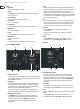
M32 DIGITAL CONSOLE User Manual 3. Rear Panel 3.3 XLR OUT 1-16 3.1 MONITOR / CONTROL ROOM OUT (1) (2) (3) (4) Outputs 1-16 Send audio to external equipment using XLR cables. Outputs 15 and 16 by default carry the main stereo bus signals. (1) External Lamp Socket Connect an external lamp via a standard 12 V / 5 W socket. (2) / (3) XLR Left & Right Sockets Connect a pair of studio monitors using standard XLR cables.
M32 DIGITAL CONSOLE User Manual 3.7 MIDI 3.9 ULTRANET MIDI IN / OUT Send and receive MIDI information via standard 5-pin DIN cables. Connect to a personal monitoring system (e.g. the Behringer P16) via Ethernet cable. 3.8 AES / EBU OUT 3.10 AES50 Send digital audio via 3-pin AES/EBU XLR cable. Transmit up to 96 channels in and out via Ethernet cables. 3.11 AUX IN / OUT (1) (2) (3) Connect to and from external equipment via ¼" or RCA cables.
M32 DIGITAL CONSOLE User Manual 4. Appendices 4.1 Appendix A: Technical Specifications Processing Input Processing Channels 32 Input Channels, 8 Aux Channels, 8 FX Return Channels Output Processing Channels 8 / 16 16 aux buses, 6 matrices, main LRC 100 Internal Effects Engines (True Stereo / Mono) 8 / 16 Internal Show Automation (structured Cues / Snippets) 500 / 100 Internal Total Recall Scenes (incl.
M32 DIGITAL CONSOLE User Manual Input/Output Characteristics Frequency Response @ 48 kHz Sample Rate 0 dB to -1 dB 20 Hz – 20 kHz Dynamic Range, Analogue In to Analogue Out 106 dB 22 Hz - 22 kHz unweighted A/D Dynamic Range, Preamplifier and Converter (Typical) 109 dB 22 Hz - 22 kHz unweighted D/A Dynamic Range, Converter and Output (Typical) 109 dB 22 Hz - 22 kHz unweighted Crosstalk Rejection @ 1 kHz, Adjacent Channels 100 dB Output level, XLR Connectors (Nominal / Maximum) +4 dBu / +21 dB
M32 DIGITAL CONSOLE User Manual 4.2 Appendix B: MIDI Operation MIDI RX > Scenes Whenever Program Change messages in the range 1-100 are received on MIDI CH01, the corresponding scene of the M32 internal show memory will be loaded.
M32 DIGITAL CONSOLE User Manual For Program Changes ‘Value’ 0…127 = program/preset number, that will be sent upon pressing the button. The MIDI commands assigned to the ASSIGN controls can be transferred to and from stage via AES50 using the S16 stage box MIDI I/O.
M32 DIGITAL CONSOLE User Manual 4.
M32 DIGITAL CONSOLE User Manual Rear View Side View
A/D AUX RETURN (1-6) SLOT (32ch OUT) AES-50 B (48ch OUT) AES-50 A (48ch OUT) SLOT (32ch IN) AES-50 B (48ch IN) AES-50 A (48ch IN) A/D PHANTOM MONITOR L+C/R+C OUT MONITOR SOURCE IN MONITOR LR OUT MAIN LRC PRE EQ OUT MAIN LRC OUT MATRIX 1-6 OUT MIX 1-16 OUT PATCH CUE MAIN LRC INSERT SEND MAIN LRC INSERT RETURN MATRIX 1-6 INSERT SEND MATRIX 1-6 INSERT RETURN MIX 1-16 INSERT SEND MIX 1-16 INSERT RETURN FX 1-8 IN (L / R) INPUT (1-32) +48V USB PLAY USB REC FX 1-8 OUT (L / R) Revision
M32 DIGITAL CONSOLE User Manual 4.5 Appendix E: Service Information This appendix contains routine service information for the M32 Digital Console. Routine Maintenance To help keep your M32 Digital Console unit in good working order and to make sure it gives you optimum performance, we recommend that you carry out the following about once every month. • Clean the control centre, as detailed in ‘Cleaning the control centre’ (below) • Check controls for freedom of operation.
M32 DIGITAL CONSOLE User Manual 4.6 Appendix F: Glossary This glossary provides an explanation of the symbols, terms and abbreviations used in this manual. 5.1 surround: A surround sound system created from six channels that form a discrete signal, which is played back over a speaker system comprising five speakers (three front and two rear) and a subwoofer (which is the ‘.1’ or LFE channel). See LFE. μ: Micro- prefix symbol that represents 10-6 or one millionth.
M32 DIGITAL CONSOLE User Manual Destination: The patch connector to which a signal is routed. See Patching. Device: A diagram(s) in the I/O tabs representing a physical rack unit, such as a line I/O, mic splitter, DN9696, AES50 etc. See Patching. DI: Abbreviation for ‘direct inject’ or ‘direct injection’. Signal is plugged directly into the audio chain without using a microphone. DI box: Device for matching signal level impedance of a source to mixer input.
M32 DIGITAL CONSOLE User Manual Mic: Abbreviation for ‘microphone’. Microphone: Device for converting sound waves into audio signals. MIDI: Acronym for ‘musical instrument digital interface’. A digital signal system standard that facilitates integration of musical instruments, such as synthesizers and guitars, with computers. Mix: 1. A signal that contains a combination of signals, such as a pair of stereo signals with numerous effects. 2. The act of creating such a combination. 3. A type of bus.
M32 DIGITAL CONSOLE User Manual Psychoacoustics: The study of the perception of sound, that is, how we listen, our psychological responses and the physiological effects on the human nervous system. Pschycoacoustic noise: Noise that affects the physiology of the listener. Q Quick access button: Button for navigation/ selection of a channel/bus/ processing area. R RAM: Abbreviation for ‘Random access memory’. Return: Auxiliary return or aux return.
M32 DIGITAL CONSOLE User Manual Other important information Important information 1. Register online. Please register your new MUSIC Group equipment right after you purchase it by visiting midasconsoles. com. Registering your purchase using our simple online form helps us to process your repair claims more quickly and efficiently. Also, read the terms and conditions of our warranty, if applicable. 2. Malfunction.
M32 DIGITAL CONSOLE User Manual 其他的重要信息 1. 在线注册。 请购买 MUSIC Group 产品后立 即在 midasconsoles. com 网站注册。 网页上有简 单的在线注册表格。 这有助于我们更快更有 效率地处理您维修等事宜。 请阅读保修的相 关条款及条件。 2. 无法正常工作。 若您的 MUSIC Group 产品 无法正常工作, 我们会为您尽快修复。 请联 系您购买产品的销售商。 若你所在地区没有 MUSIC Group 销售商, 请联系 midasconsoles. com 网站的 “ WHERE TO BUY ” 一栏下的所列出的子 公司或经销商。 3.
M32 DIGITAL CONSOLE FEDERAL COMMUNICATIONS COMMISSION COMPLIANCE INFORMATION MIDAS M32 DIGITAL CONSOLE Responsible Party Name: MUSIC Group Research UK Limited Address: Klark Industrial Park, Walter Nash Road, Kidderminster. Worcestershire. DY11 7HJ. England.
midasconsoles.