
Operation Manual


258 Chapter 30: Input Channels
PRO1 Live Audio System
Operator Manual
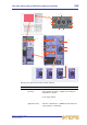
Direct output
The direct output section lets you to take a signal directly out of a defined point in the
input channel’s signal path and route it to either an internal assignable effect or a
physical output (a physical connection at one of the line I/O boxes). This function is
optional and assigned on a channel-by-channel basis.
This section is deliberately distanced from the main channel panel controls because it is
a limited resource and unused on many channels.
Selection of signal path position (item 4) and destination (item 5) can only be carried
out via the GUI.
Item Description Function
1 MUTE switch Mutes any assigned direct output by removing signal
from the output. However, it will not operate (will
remain illuminated) if nothing is assigned. It is
included in the scene recall system but is not affected
by the channel mute safe or the auto-mute masters
(unless the source tap-off point is after the main
channel mute).
2 B switch Changes the operation of the SOLO switch so that it
routes signals to the monitor B section of the control
centre.
3 SOLO switch Activates signal routing to the Monitor A (or if the B
switch is illuminated, Monitor B) section of the control
centre.
4 Tap-off point
diagram
Shows where the direct output is sourced from in the
signal path, as selected by the mode button (see
item 7).
5 dest button Opens the Patching screen so that you can select
the destination of the direct output.
1
2
3
4
5
6
7
8
9