PRO Series Live Audio Systems Owner’s Manual Midas Klark Teknik Limited, Klark Industrial Park, Walter Nash Road, Kidderminster. Worcestershire. DY11 7HJ. England. Tel: +44 1562 741515 Fax: +44 1562 745371 Email: info@midasklarkteknik.com Website: www.midasconsoles.com PRO Series Live Audio Systems — Owner’s Manual DOC02-PROSERIES Issue A — September 2010 © Red Chip Company Ltd.
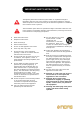
IMPORTANT SAFETY INSTRUCTIONS The lightning flash with arrowhead symbol within an equilateral triangle is intended to alert the user to the presence of uninsulated “dangerous voltage” within the product's enclosure that may be of sufficient magnitude to constitute a risk of electric shock to persons. The exclamation point within an equilateral triangle is intended to alert the user to the presence of important operating and maintenance (servicing) instructions in the literature accompanying the product.
INSTRUCTIONS DE SÉCURITÉ IMPORTANTES Le symbole représentant un éclair fléché dans un triangle équilatéral a pour but d'alerter l'utilisateur de la présence d'une "tension dangereuse" non isolée à l'intérieur du boîtier, pouvant être d'une force suffisante pour constituer un risque d'électrocution.
PRO6 EC-Declaration of Conformity Midas EC-Declaration of Conformity The undersigned, representing the following manufacturer Manufacturer: Address: Midas Klark Teknik Ltd. Klark Industrial Park, Walter Nash Road, Kidderminster. Worcestershire. DY11 7HJ. hereby declares that the following product Product Type Number Product Description Nominal Voltage(s) Current Freq. PRO3 Control Centre 115V AC 230V AC 2.9A 1.
PRO6 EC-Declaration of Conformity Midas EC-Declaration of Conformity The undersigned, representing the following manufacturer Manufacturer: Address: Midas Klark Teknik Ltd. Klark Industrial Park, Walter Nash Road, Kidderminster. Worcestershire. DY11 7HJ. hereby declares that the following product Product Type Number Product Description Nominal Voltage(s) Current Freq. PRO6 Control Centre 115V AC 230V AC 2.9A 1.
PRO9 EC-Declaration of Conformity Midas EC-Declaration of Conformity The undersigned, representing the following manufacturer Manufacturer: Address: Midas Klark Teknik Ltd. Klark Industrial Park, Walter Nash Road, Kidderminster. Worcestershire. DY11 7HJ. hereby declares that the following product Product Type Number Product Description Nominal Voltage(s) Current Freq. PRO9 Control Centre 115V AC 230V AC 2.9A 1.
Licences The following are the license agreements applicable to the Midas Digital Equipment. End-User Licence Agreement for Midas™ and Klark Teknik™ Software IMPORTANT - Please read this document carefully before using this Midas™ or Klark Teknik™ Product. This is an agreement governing your use of software or other machine instructions already installed on this Midas™ or Klark Teknik™ Product, as well as other software that we provide for installation on this Product.
DATE INFORMATION. You understand that the Company may update or revise the Software but in so doing incurs no obligation to furnish such updates to you. However, the Company may in its discretion make updates available from time to time upon such terms and conditions as it shall determine.
and the Courts of England and Wales will have exclusive jurisdiction to hear and decide any dispute concerning it or its formation. No breach by you of any provision of this Licence shall be waived or discharged except with the express written consent of the Company and no failure or delay by the Company to exercise any of its rights under this Licence shall operate as a waiver thereof and no single or partial exercise of any such right shall prevent any other or further exercise of that or any other right.
xvii Precautions Before installing, setting up or operating this equipment make sure you have read and fully understand all of this section and the “IMPORTANT SAFETY INSTRUCTIONS” at the front of this document. This equipment is supplied by a mains voltage that can cause electric shock injury! The following must be observed in order to maintain safety and electromagnetic compatibility (EMC) performance. Safety warnings Signal 0V is connected internally to the chassis.
xviii Handling the equipment Completely isolate the equipment electrically and disconnect all cables from the equipment before moving it. Precautions the equipment, making sure that its fans and vents are not obstructed. Whenever possible, keep the equipment out of direct sunlight. Do not place the equipment in an unstable condition where it might accidentally fall over. When lifting or moving the equipment, always take its size and weight into consideration.
xix Precautions not installed and used in accordance with the instruction manual, may cause harmful interference to radio communications. Operation of this equipment in a residential area is likely to cause harmful interference in which case the user will be required to correct the interference at his own expense.
xx Precautions PRO Series Live Audio Systems Owner’s Manual
xxi Recommandations Avant l'installation, la mise au point ou l'exploitation de cet équipement, veiller à lire attentivement et à comprendre l'intégralité de ce chapitre et la partie "CONSIGNES DE SÉCURITÉ IMPORTANTES" au début de ce manuel. Cet équipement est alimenté par une tension de secteur pouvant provoquer des blessures par choc électrique ! Les points suivants doivent être observés afin de maintenir la sécurité et une compatibilité électromagnétique (CEM) correcte.
xxii Manipulation de l'équipement Isoler électriquement et totalement l'appareil et débrancher tous ses câbles avant de le déplacer. En soulevant ou en déplaçant l'appareil, tenir toujours compte de sa taille et de son poids. Utiliser un dispoitif de levage adapté ou un matériel de transport, ou encore suffisamment de personnel supplémentaire. Ne pas introduire les doigts ni les mains dans les fentes ni les ouvertures de l'appareil, telles que les ouïes de ventilation.
xxiii Recommandations Interférences radioélectriques - Dispositif de Classe A Cet équipement a été testé et est conforme aux limites d'un produit numérique de Classe A, en application de la Partie 15 des Règles de la FCC. Ces limites sont destinées à assurer une protection raisonnable contre les interférences néfastes lorsque l'équipement fonctionne dans un environnement commercial.
xxiv Recommandations PRO Series Live Audio Systems Owner’s Manual
xxv Contents Cover page ........................................... i Information page . . . . . . . . . . . . . . . . . . . . . . . . . . . . . . . . . . . . . . . . . . iii IMPORTANT SAFETY INSTRUCTIONS . . . . . . . . . . . . . . . . . . . . . . . . . . . . v INSTRUCTIONS DE SÉCURITÉ IMPORTANTES . . . . . . . . . . . . . . . . . . . . . vi PRO6 EC-Declaration of Conformity . . . . . . . . . . . . . . . . . . . . . . . . . . . . vii PRO6 EC-Declaration of Conformity . . . . . . . . . . . . . . . . . .
xxvi Contents System components . . . . . . . . . . . . . . . . . FOH and MON . . . . . . . . . . . . . . . . . . . . . . System buses . . . . . . . . . . . . . . . . . . . . . . Mix matrix . . . . . . . . . . . . . . . . . . . . . . . . Processing . . . . . . . . . . . . . . . . . . . . . . . . Processing components . . . . . . . . . . . . . Input channel processing . . . . . . . . . . . . Mix channel processing . . . . . . . . . . . . . Output channel processing . . . . . . . . . . .
xxvii Contents Operating the top output fast strips from the master bay Controlling the mix buses in flip mode . . . . . . . . . . . . . Hints and tips . . . . . . . . . . . . . . . . . . . . . . . . . . . . . . . . Saving your work . . . . . . . . . . . . . . . . . . . . . . . . . . . . . . Saving a show versus storing a scene . . . . . . . . . . . . . . Shutting down the control centre properly . . . . . . . . . . Chapter 6 . . . . . . . . . . . . . . . . . . . . . . . . . . . . . . . 48 . 48 .
xxviii Contents Automatic patching (AUTO) . . . . . . . . . . . . . . . . . . . . . . . . . . . . .97 Clearing all current patching . . . . . . . . . . . . . . . . . . . . . . . . . . . .98 Chapter 9 Basic Operation . . . . . . . . . . . . . . . . . . . . . . . . . . . . . 99 Setting a mic amplifier’s input gain . . . . . . . . . . . . . . . . . . Setting the high and low pass filters . . . . . . . . . . . . . . . . . Input equalisation (E zone) . . . . . . . . . . . . . . . . . . . . . . .
xxix Contents Chapter 12 Soloing . . . . . . . . . . . . . . . . . . . . . . . . . . . . . . . . . . . 137 Using solo A/B . . . . . . . . . . . . . . . . . . . . . . . . . . . . . . . . . . . . . . . 137 Solo hierarchy . . . . . . . . . . . . . . . . . . . . . . . . . . . . . . . . . . . . . . . 139 Solo in place (SIP) . . . . . . . . . . . . . . . . . . . . . . . . . . . . . . . . . . . . 139 Chapter 13 Chapter 14 Muting . . . . . . . . . . . . . . . . . . . . . . . . . . . . . . . . . . .
xxx Chapter 17 Contents Control Groups . . . . . . . . . . . . . . . . . . . . . . . . . . . . 177 VCA and POP groups . . . . . . . . . VCA fast strips . . . . . . . . . . . POP groups . . . . . . . . . . . . . Working with VCA/POP groups Auto-mute (mute) groups . . . . . Talk groups . . . . . . . . . . . . . . . About the control group screens . Management section . . . . . . . Programming the groups . . . . . . Configuring the groups . . . . . . . Chapter 18 . . . . . . . . . . . . . . . . . . . . .
xxxi Contents Chapter 21 Scope (Automation) . . . . . . . . . . . . . . . . . . . . . . . . . 213 About scope . . . . . . . . . . . . . . . . . . . . . . . . . . About the Recall Scope screen . . . . . . . . . . . . . Selecting scope parameter sections . . . . . . . . . Selecting bus parameters . . . . . . . . . . . . . . Saving scope parameters in a scene . . . . . . . . . Using store scope . . . . . . . . . . . . . . . . . . . . . . Chapter 22 .... .... .... .... .... .... .... .... .... . . . . . .
xxxii Contents Changing the signal processing preferences . . . . . . Configuring the channels, groups and internal units Changing the default input/output names . . . . . . . Adjusting PRO Series illumination . . . . . . . . . . . . . Setting the time and date . . . . . . . . . . . . . . . . . . . Chapter 28 . . . . . . . . . . . . . . . . . . . . . . . . . . . . . . . . . . . . . . . . . . . . . . . . . . . . . . . . . . . . .250 .251 .251 .251 .252 Delay Compensation (Latency) . . . . .
xxxiii Contents Gate . . . . . . . . . . . . . . . . . . . . . Side chain . . . . . . . . . . . . . . . . . Insert . . . . . . . . . . . . . . . . . . . . . . EQ (E zone) . . . . . . . . . . . . . . . . . . EQ graph . . . . . . . . . . . . . . . . . Mixes . . . . . . . . . . . . . . . . . . . . . . Master controls, solo/mute and fader Masters sections and pan control . LCD select button . . . . . . . . . . . . Mute, solo and safes . . . . . . . . . . Fader . . . . . . . . . . . . . . . . . . . .
xxxiv Contents Appendices Appendix A Application Notes . . . . . . . . . . . . . . . . . . . . . . . . . . 341 Spatial imaging system (SIS™) . . . . . . . . . . . . . . . . . . . . . . . . . . . .341 PRO Series compressor modes (dynamic) . . . . . . . . . . . . . . . . . . . .341 Description . . . . . . . . . . . . . . . . . . . . . . . . . . . . . . . . . . . . . . .341 Compressor envelope modes . . . . . . . . . . . . . . . . . . . . . . . . . . .343 PRO Series input channel EQ modes . . . . . . . . .
xxxv Contents Appendix C Klark Teknik DN370 GEQ . . . . . . . . . . . . . . . . . . . . . 369 Notes . . . . . . . . . . . . . . . Using the GEQ . . . . . . . . . Studio and creative use Live use (MON) . . . . . . Bypassing the EQ . . . . . Audio signal path . . . . . . . Appendix D . . . . . . . . . . . . . . . . . . . . . . . . . . . . . . . . . . . . . . . . . . . . . . . . . . . . . . . . . . . . . . . . . . . . . . . . . . . . . . . . . . . . . . . . . . . . . . . . . . . . . . . . .
xxxvi Contents Troubleshooting automation . . Error messages . . . . . . . . Error condition messages . . Error description messages Appendix H . . . . . . . . . . . . . . . . . . . . . . . . . . . . . . . . . . . . . . . . . . . . . . . . . . . . . . . . . . . . . . . . . . . . . . . . . . . . . . . . . . . . . . . . . . . . . . . . . . . . . . . . .399 .399 .400 .401 Updating PRO Series Host Software . . . . . . . . . . . .
xxxvii Contents Matrices . . . . . Patching . . . Configuration Dynamics . . Insert . . . . . EQ . . . . . . . Aux send . . Aux preset . Matrix send . Fader . . . . . Masters . . . . . . Patching . . . Configuration Dynamics . . Insert . . . . . EQ . . . . . . . Aux send . . Aux preset . Matrix send . Fader . . . . . GEQ rack . . . . . Patching . . . GEQ . . . . . . Effects rack . . . Patching . . . Effects . . . . Groups . . . . . . Appendix L . . . . . . . . . . . . . . . . . . . . . . . . . . . . .
xxxviii Contents AUTO (automation) safe . . . . . . . . . . . . . . . . . . . . . . . . . . . MUTE safe . . . . . . . . . . . . . . . . . . . . . . . . . . . . . . . . . . . . . FADER safe . . . . . . . . . . . . . . . . . . . . . . . . . . . . . . . . . . . . Returns (Aux Returns) . . . . . . . . . . . . . . . . . . . . . . . . . . . . . . . Return parameters not affected by the safes . . . . . . . . . . . . . EQ safe . . . . . . . . . . . . . . . . . . . . . . . . . . . . . . . . . . . . . . .
xxxix Contents Return . . . . . . . Configuration . Compressor . . Gate . . . . . . . EQ . . . . . . . . Bus sends . . . Master routing Matrix . . . . . . . . Configuration . Compressor . . Gate . . . . . . . EQ (GEQ) . . . Bus sends . . . Fader section . Master . . . . . . . Configuration . Compressor . . Gate . . . . . . . EQ (GEQ) . . . Bus sends . . . Master routing Appendix O . . . . . . . . . . . . . . . . . . . . . . . . . . . . . . . . . . . . . . . . . . . . . . . . . . . . . . . . . . . . .
xl Contents Filters . . . . . . Dynamics . . . . Insert . . . . . . EQ . . . . . . . . Bus sends . . . Master routing Fader . . . . . . Delay . . . . . . Matrix . . . . . . . . Input controls . Direct output . Direct input . . Filters . . . . . . Dynamics . . . . Insert . . . . . . EQ . . . . . . . . Bus sends . . . Master routing Fader . . . . . . Delay . . . . . . Master . . . . . . . . Input controls . Direct output . Direct input . . Filters . . . . . . Dynamics . . . . Insert . . . . . . EQ . . . . .
xli Contents Fader Sections . . . . . . . Recall Scope . . . . . . . . Store Scope . . . . . . . . Routing . . . . . . . . . . . . Aux Sends (aux channels) . Config sections . . . . . . Comp./Output Dyn . . . . Gates . . . . . . . . . . . . . EQs . . . . . . . . . . . . . . Aux Sends (1 to 16) . . . Matrix Sends (1 to 16) . Fader Sections . . . . . . . Recall Scope . . . . . . . . Store Scope . . . . . . . . Routing . . . . . . . . . . . . Matrix (matrix channels) . . Config sections . . . . . . Comp.
xlii Contents PRO Series Live Audio Systems Owner’s Manual
Overview Volume 1: PRO Series Live Audio Systems Owner’s Manual
3 Chapter 1: Introduction Welcome to the PRO Series Live Audio Systems. The PRO Series, which comprises the PRO3, PRO6 and PRO9, provide user-friendly, state-of-the-art, high performance digital systems specifically designed for live use.
4 Chapter 1: Introduction Conventions • Hand symbols, such as, (pushbutton, trackball etc.) and (control knob), are used to show the operation of the physical controls on the control surface. GUI operation is indicated by a pointer , which represents a ‘click’ operation. • The graphics shown right are used to differentiate between diagrams of the control surface (immediate right) and GUI (far right). Placement is generally towards the upper-right corner of the diagram.
5 Training GUI diagrams This manual contains numerous diagrams that represent the GUI screen displays. Due to the many permutations of control settings, operating status, channel configurations etc., it is inevitable that these diagrams will look slightly different to those on your control centre. Anti-aliasing To make the GUI of the PRO Series as crisp, eye-catching and as intelligible as possible it incorporates an anti-aliasing algorithm to ensure the utmost smoothness of straight lines and curves.
6 Chapter 1: Introduction PRO Series Live Audio Systems Owner’s Manual
7 Chapter 2: PRO Series Live Audio Systems This chapter gives an overview of the PRO Series Live Audio Systems. Introducing the PRO3 The PRO3 Live Audio System is an entry-level system that is ideally suited to situations requiring tighter budgets, enabling more touring riders and professional installations to take advantage of Midas’ digital features. The PRO3 Live Audio System has 56 input channels with remote controlled mic preamps, 27 buses and six stereo effects.
8 Chapter 2: PRO Series Live Audio Systems Overview A PRO Series Live Audio System is a very powerful and flexible audio processing system that provides a complete solution for any audio mixing and signal distribution application in a live sound environment. The PRO Series Live Audio Systems comprise the PRO3, PRO6 and PRO9 and their common features include: • Dual ‘daylight visible’ screens with three-way KVM switch. • XL8-style ‘fast zones’. • XL8-style dual operator ‘channel strips’. • 10 VCAs.
9 Key features I/O unit(s) are dependent on system type. The PRO Series Control Centre and rack units are interconnected by a networked data system, which carries both proprietary control data and open architecture AES50 digital audio, and uses readily available standard cabling and connectors. The PRO Series uses a proven stable Linux operating system. All of the control centre’s internal and network routing (“patching”) is managed via the graphical user interface (GUI).
10 Chapter 2: PRO Series Live Audio Systems • EQ — Fully interpolated phase shifting EQ for that “Midas” sound. • PEQ — High quality EQ with the “Midas” sound. Each output has a six-band parametric EQ, while the inputs have four bands each. Midas sound quality and ‘feel’ on the EQ’s four filters. • GEQ — Up to 36 Klark Teknik-quality GEQs with unique on-board fast access controller and control from RapidE. • Effects — High quality effects processing with traditional artefacts.
11 Key features • • Reliability — High reliability with some redundancy and other back up contingencies. • Failure-tolerant of any single failure of hardware or software. • Proven, stable Linux operating system. • Dual redundant control surface master controllers and N+1 redundant PSUs. • Duplicated (N+1) network for redundancy. • Control centre has triple redundant power supplies. • DL251 Audio System I/O (stage box) has dual redundant power supplies.
12 Chapter 2: PRO Series Live Audio Systems Item PRO3 PRO6 PRO9 Standard surface I/O (three configurable card slots): see Table 3 “Standard equipment supply per PRO Series system” on page 16 Yes Yes Yes Stage I/O DL251 - 48 inputs and 16 outputs, fixed configuration DL351 - 56 inputs and 8 outputs, configurable I/O DL351 - 56 inputs and 8 outputs, configurable I/O DL451 - 24 inputs, configurable I/O Digital snake 100 m bi-directional 192 + 192 channel Cat 5e digital snake (with redundant opti
13 Applications Item PRO3 PRO6 PRO9 Control centre flight case Yes N/A N/A 16U flight case for DL371 DSP and I/O Yes N/A N/A Klark Teknik DN9331 Rapide Graphic Controller Yes Yes Yes Klark Teknik DN9696 Recorder Yes Yes Yes Klark Teknik DN9650 Network Bridge (MADI, Dante, Aviom, Ethersound, CobraNet) Yes Yes Yes Packing options: Accessories: * Packing may vary by territory.
14 Chapter 2: PRO Series Live Audio Systems System components The PRO Series are modular systems, which allows for some variations in physical placement and system size. The standard PRO Series touring system package is shipped in a single, easily portable flight case, with an equally portable, flight-cased control surface and minimal cabling. The following table lists all of the available equipment options for the PRO Series Live Audio System package.
15 System components Item Example DL371 Audio System Engine This is populated with five cards, the two empty slots being blanked off. (If the optional N+1 redundant DSP module card is fitted, there will be six cards and one empty slot.) DL431 Mic Splitter This is a fixed configuration I/O unit that has 24 mic/line inputs in a 5-way split. DL451 Modular I/O This gives up to 24 configurable I/Os in a 3 x 8 XLR modular format. DL441 analogue input (mic) module This is an analogue mic/line input "I" card.
16 Chapter 2: PRO Series Live Audio Systems Table 3: Standard equipment supply per PRO Series system Item PRO3 PRO6 PRO9 Control centre Thee slots in rear panel populated with: DL443 module and two blank panels. Thee slots in rear panel populated with the following modules: DL442, DL443 and DL452 Thee slots in rear panel populated with the following modules: DL442, DL443 and DL444 Control centre supplied in ...
17 FOH and MON Item PRO3 PRO6 PRO9 Interconnecting (dual redundant) gigabit HyperMac Cat 5e copper cable, 100 m long. 2-off 2-off 2-off Mains cable 8-off 8-off 8-off FOH and MON Each PRO Series can be used as a front of house (FOH) or stage monitor (MON) system. System buses The PRO Series has comprehensive system buses to suit demanding applications, comprising: • 6-off solo buses, routable from all locations and allowing for dual operator and 5.1 use.
18 Chapter 2: PRO Series Live Audio Systems Mix matrix Ultimately, the mix matrix defines the capability of each PRO Series Control Centre. Probably the best way to imagine the mix matrix is to think of an analogue console layout, where inputs run vertically and buses run horizontally. A mix matrix is usually defined as the number of buses and the quantity of simultaneously-mixable inputs there are per bus. The following diagrams illustrate the capability within each PRO Series Control Centre.
19 Mix matrix 8 mic/line return inputs { 64 in x 16 out mix matrix } { 80 in x 3 out mix matrix } 16 matrix buses { 83 in x 16 out mix matrix } 6 solo buses { 99 in x 6 out mix matrix } { 88 in x 16 out mix matrix } { 104 in x 3 out mix matrix } 107 in x 16 out mix matrix } 16 aux buses Bus inputs 3 master (stereo and mono) buses Bus outputs 56 mic/line inputs Figure 2: PRO6 mix matrix 8 mic/line return inputs Bus inputs 16 aux buses 3 master (stereo and mono) buses Figure
20 Chapter 2: PRO Series Live Audio Systems Processing Although the control centre system allows for considerable insertion of external processing, it also embodies more than enough internal high quality processing to eliminate the need for this, in the interests of simplicity and reduced overall system size, weight and cost. Processing components The processing available is: • Up to 80 x 12 or 24dB/oct. high pass filters. • Up to 80 x 6 or 12dB/oct. low pass filters.
21 Processing • EQ. • Fader. • Panpot (SIS™). • Routing via level controls to the matrix buses (8 or 16). • Routing via pan control to the left, right and mono master buses. Mix channel processing Each of the 16 auxiliary mix buses has: • Subgroup, auxiliary or mix minus modes. • Dual mono or stereo pair modes. • Six-band PEQ. • Optional 31-band GEQ (replaces PEQ). • Frequency-conscious compressor with choice of five compression styles. • Insert point.
22 Chapter 2: PRO Series Live Audio Systems Effects processing and GEQs The PRO Series contains six or eight mono Klark Teknik (KT) GEQs and seven effects processors as standard. The seven effects processors can be freely chosen from: • KT DN780 reverb. • Delay. • Flanger. • Phaser. • Pitch shifter. • SQ1 dynamics. • Stereo 3-band compressor. The six or eight mono KT GEQs can be patched into any output.
23 Network Three additional surround modes operate as follows: • Quad Left – Right – LS – RS routing to matrices 1, 2, 5 and 6. • Surround • 5.1 surround Left – Right – Centre – Sub – LS – RS routing to matrices 1, 2, 3, 4, 5 and 6. Left – Right – Centre – Surround routing to matrices 1, 2, 3, 5 and 6.
24 Chapter 2: PRO Series Live Audio Systems GUI The PRO Series has two, daylight-viewable, TFT screens that provide fast zone and channel strip status indication. Although any screen can display any information, in the standard configuration, screen information relates to module location. So, the mix bay screen displays the channel strip and fast zone (12 inputs and 16 outputs), while the master bay screen displays the channel strip, input fast zone (four inputs) and all meters.
Integration of third party hardware/software • Wireless mic controllers. • Your email. • DVD movies.
26 Chapter 2: PRO Series Live Audio Systems PRO Series Live Audio Systems Owner’s Manual
27 Chapter 3: About The Control Centre This chapter introduces you to the control centre and provides a brief hardware description. Overview of the control centre The control centre has a combined control surface and GUI that provide an array of easy-to-use controls for the precise manipulation of audio. The control centre is of modular construction and is built on a robust Midas steel frame chassis similar to those used for established Midas analogue products.
28 Chapter 3: About The Control Centre the GUI screens can be used to operate the whole control centre, even if none of the control surface hardware is working. The unit offers the facility of universal input, N+1 redundant power supplies with three latching mains connectors.
29 Control surface Control surface The control surface is divided into areas whose function is, largely, dependent on bay location. Each bay has assorted control elements with local feedback and/or support from the two centrally located GUI display screens. The screens can be remoted via external VGA connections, and third party systems can also be viewed/controlled via an integrated KVM switch on the rear panel.
30 Chapter 3: About The Control Centre During show time the screen functions that require fast access are controlled by control knobs, pushbutton switches, faders etc. More complex functions that do not require this fast access are controlled by the trackballs and navigational keys. A keyboard integral to the flight case is used for text entry via the master bay GUI screen. An external USB keyboard can be used to operate the mix bay GUI screen.
31 Front and rear panel connections Each GUI screen has its own default display, although either is selectable via the GUI main menu. The Overview screen displays 12 inputs and two sets of eight outputs, and the Meters screen shows all the meters, four inputs and a summary of the automation. Both screens have a banner at the top, which is constantly displayed, and a channel strip down the outermost side.
32 Chapter 3: About The Control Centre External interfaces and peripheral devices Various devices can be used with the PRO Series, such as: • External USB mouse Instead of using the primary navigation zone to operate either of the GUI screens, you can use an external USB mouse. This can be plugged into any of the USB connectors on the PRO Series. The USB mouse behaves in the same way as any PC mouse. For more information, see “Using an external USB mouse” on page 244.
Automation 33 For details of the bus types and their options, see Table 24 “Definition of primary buses” on page 417. Automation The automation system can store and recall up to 1000 snapshot scenes. These contain the setting values for every control on the control centre (excluding some of the monitor section). Scene recall (and store) can be ‘scoped’ such that only the areas that you want to recall (or store) are affected, while all other controls remain in their current state.
34 Chapter 3: About The Control Centre PRO Series Live Audio Systems Owner’s Manual
Volume 1: Getting Started PRO Series Live Audio Systems Owner’s Manual
37 Chapter 4: Setting Up The System This chapter shows you how to set up a live audio system to its default configuration. Note: If you want to set up the system using a configuration other than the default, please contact Midas Technical Support for details. Initial set-up procedure Initial system set-up basically comprises: • Unpacking and checking the equipment — see “Unpacking the equipment” on page 37. • Making up a rack — see “Making up a rack” on page 37.
38 Chapter 4: Setting Up The System through the rear. Situations where the air flows in a circular direction around and through a PRO Series unit must be prevented. Midas recommends that racks with fully opening front and rear doors are used. Caution! Never combine units in the same rack that have been designed for a ventilation air flow direction other than that designed for the Midas units. To avoid this, we recommend that any non-Midas units are housed separately.
39 Wiring instructions PRO3 Control Centre (control surface, router, 8 x inputs, 8 x outputs, 8 x insert Jack I/O pairs and 6 x monitor outputs) 3 x AES50 expansion ports Cat 5e snakes (100 m, bi-directional, 192 + 192-channel) Mix position Stage Rack (the DL251 and DL371 units are typically located in a single 14U rack) DL371 Audio System Engine (4 x AES50 expansion ports) DL251 Audio System I/O (48 x inputs and 16 x outputs) Figure 7: Standard PRO3 system configuration PRO Series Live Audio Syste
40 Chapter 4: Setting Up The System PRO6 Control Centre (control surface, router, 8 x inputs, 8 x outputs, 8 x insert Jack I/O pairs and 6 x monitor outputs) 3 x AES50 expansion ports Copper Fibre optic Mix position Stage Dual cable redundant HyperMAC (fibre optic or copper) Rack (the DL351 and DL371 units are typically located in a single 14U rack) DL371 Audio System Engine (4 x AES50 expansion ports) Maximum 100 m, typically 0.
41 Wiring instructions PRO9 Control Centre (control surface, router, 8 x inputs, 8 x outputs, 8 x insert Jack I/O pairs and 6 x monitor outputs) 3 x AES50 expansion ports Copper Fibre optic Mix position Stage Dual cable redundant HyperMAC (fibre optic or copper) Rack (the DL351, DL371 and DL451 units are typically located in a single 14U rack) DL371 Audio System Engine (4 x AES50 expansion ports) Maximum 100 m, typically 0.
42 Chapter 4: Setting Up The System Powering the system The following details the recommended power up and power down procedures for the system. Note: If you are in any doubt as to how to switch the rack units on/off, refer to their operator manuals. >> To power up the system Important Note: DO NOT switch on the speaker sub-system until after the start-up of the system has been completed.
43 Switching the control centre on/off Switching the control centre on/off Carry out the following to switch the control centre on or off in a safe manner, observing all WARNINGS and Cautions. >> To switch on the control centre Caution (1)! A minimum of two power supply modules must be supplying power to the control centre for correct operation. Caution (2)! Before switching on, check that all monitor loudspeaker power amplifiers are turned off or muted.
44 Chapter 4: Setting Up The System Setting up the ID of the unit(s) After connecting up your system, you may need to set up the ID of the unit(s) in the rack, such as the DL351 Modular I/O, DL451 Modular I/O or DL431 Mic Splitter, as each unit must have its own unique ID number. (This does not apply to the DL251 Audio System I/O.) Note: The I/O unit doesn’t have to be connected in the system for you to set up its ID, as the procedure can be carried out offline.
Basic Operation Of The PRO Series Volume 2: PRO Series Live Audio Systems Owner’s Manual
47 Chapter 5: Before You Start This chapter is intended to familiarise you with the control centre by showing you how to carry out some basic operations in order to get some audio out of it. Note: As the operation of both input bays is principally the same, this chapter will generally only show the operation of the 12-channel input bay. However, any differences in operation between the 4-channel and 12-channel input bays will be shown.
48 Chapter 5: Before You Start Operating the top output fast strips from the master bay During normal operation, both rows of output fast strips — which are always independent from each other — are operated using the controls in the mix bay. However, you can assign the master bay to control the top row of output strips. >> To switch control of the output strips to the master bay Press the right arrow (to right channel) button (see Figure 12 “Output channel navigational controls” on page 66).
Saving your work 49 Saving your work We recommend that you save your work regularly while carrying out the procedures included in this chapter. Not only is this good practise during normal operation, but in this instance it may save you from losing some set-ups that could prove useful later on. To do this, create a new show (see “To open the Automation screen” on page 112), and then continue reading through the remainder of this section, following the instructions carefully.
50 Chapter 5: Before You Start PRO Series Live Audio Systems Owner’s Manual
51 Chapter 6: Working With The Control Centre This chapter is intended to familiarise you with control surface and GUI controls of the control centre. Although nearly all of the operations done via the control surface of the PRO Series Control Centre can be replicated via the GUI, the emphasis in this chapter — and throughout the manual — is on the former method. This is because, generally, control surface operation is quicker and more intuitive than using the GUI.
52 Chapter 6: Working With The Control Centre Type Description Example(s) LED Show status indication. An illuminated LED shows an active (on) or enabled condition and, when extinguished, it indicates an off or disabled condition. Meter All of the input fast strips, master fast strips and monitors have a peak level meter. There are also ones for the centre speaker and subwoofer of the 5.1 surround panning. In addition, each input fast strip has a gain reduction meter for both the compressor and gate.
53 Common GUI screen elements The GUI is operated via the primary navigation zone and is principally the same as using a laptop PC, although you can operate either screen using an external USB mouse instead (see “Using an external USB mouse” on page 244). A USB keyboard is plugged into the PRO Series for text editing. Each trackball controls the movement of a pointer on its respective GUI screen (see Figure 9).
54 Chapter 6: Working With The Control Centre Parameter values displayed on touch You can configure the PRO Series (see “Changing the user interface preferences” on page 250) so that the GUI displays the current value (and dimension) of the control being adjusted. Operating the GUI screen controls This section shows you how to operate GUI screen elements, such as buttons, control knobs, drop-down lists and sliders. >> To switch a GUI button on/off Click the button.
55 Operating the GUI screen controls Spin buttons Up/down spin buttons let you increase/decrease the attribute or value of an item. For example, the amount of time a signal is delayed (see “Input channel delay (GUI only)” on page 284).
56 Chapter 6: Working With The Control Centre Using the GUI menu You can open the GUI menu at either GUI screen or you can go directly a GUI menu screen by using a screen access button. Throughout this manual, menu/submenu option selection sequences are shown in the following format (for example, for choosing the general preferences screen): home Preferences General >> To open the GUI menu Click home.
57 Text editing >> To open a GUI menu screen using a screen access button In the primary navigation zone, press a screen access button to open the first screen (printed to the right of the button). Press it again to open the second screen. These two examples show you how to use the screen access buttons to open the Automation screen (single press) and the Graphic EQs screen (two presses). These buttons take you directly to the screen you want.
58 Chapter 6: Working With The Control Centre PRO Series Live Audio Systems Owner’s Manual
59 Chapter 7: Navigation This chapter introduces you to navigation on the control centre and shows you how to use its navigational tools. For information on navigating the scenes in automation, refer to “Managing the scenes” on page 114. An introduction to navigation The control centre provides you with unique navigational controls to quickly and easily access the items, such as channels, buses, groups and processing areas, that you will require for mixing.
60 Chapter 7: Navigation Mix bay channel strip PRO3 and PRO6 PRO9 8 9 7 7 Input fast strip 6 10 PRO3 and PRO6 10 1 PRO9 8 9 7 7 2 6 11 12 5 3 4 VCA Figure 10: Input channel navigational controls Item Element(s) Description 1 Quick access button — channel strip Quickly selects the local processing area of the selected channel or channel pair, but doesn’t affect channel selection. Illuminates (blue) when active.
61 Navigating the input channels Item Element(s) Description 3 LCD select button — input fast strip Selects the local input channel. Has a backlit LCD display (with user-configurable backlight colour), which shows channel name etc. When selected, the display changes to a ‘negative’ image. 4 LCD select button — VCA/ POP group Selects the VCA/POP group, unfolding the group members to the control surface. Has a backlit LCD display (with user-configurable backlight colour), which shows group name.
62 Chapter 7: Navigation D A B C To cater for the higher channel count of the PRO9 the LEDs to the right of the input select section (A and C) illuminate to show whether the numbered LEDs to the left are referring to the lower (B) or higher (D) numbered banks of inputs, respectively. >> To assign an input channel to the control surface Do one of the following: • Scroll buttons Scroll the desired input channel to the control surface using the scroll by 4 buttons in the input select section.
Navigating the input channels 63 >> To select a processing area You may want a specific processing area of an input channel assigned to the local channel strip, for example, to carry out processing or for copying its parameters to another input channel. Do one of the following: • Quick access button (channel strip) If the input channel you want is currently selected at the control surface, press the quick access button local to the desired processing area in the channel strip.
64 Chapter 7: Navigation Navigating the mix buses The input channels each have aux and matrix mix buses. Mix sections (master bay) Mix sections (mix bay) Input fast strip 1 5 5 6 4 3 4 2 3 2 Figure 11: Mix bus navigational controls Item Element(s) Description 1 Quick access button — input fast strip This button in the mix section of the input fast strips quickly selects the local mix area of the selected channel. Illuminates (blue) when active.
65 Navigating the mix buses Item Element(s) Description 5 Display Shows the number of the currently selected mix bus and its type. 6 FLIP button See “Controlling the mix buses in flip mode” on page 48. >> To navigate a mix bus to the control surface Do one of the following: • Scroll to the desired mix bus using the scroll by 1 buttons in the mix section. Mix bus selection follows the scrolling.
66 Chapter 7: Navigation Navigating the output channels The output channels comprise auxes, returns, matrices and masters. Master bay channel strip Output fast strip 3a 4 3 5 3a 2 1 6 8 Master channels 7 Figure 12: Output channel navigational controls Item Element(s) Description 1 Quick access button — master channels Quickly selects the local master channel. Illuminates (blue) when active. 2 Quick access button — output fast strip Quickly selects the local output channel.
67 Navigating the output channels Item Element(s) Description 3 Channel select buttons Each button assigns its bank of channels to the eight output fast strips to the left. PRO3 only: The MTX buttons (3a) for output channels 9 to 16 are not used. 4 Right arrow button See “Operating the top output fast strips from the master bay” on page 48.
68 Chapter 7: Navigation You can use the GUI menu to select any output channel you want via the home Mix & Outputs option. >> To select a processing area You may want a specific processing area of an output channel assigned to the local channel strip, for example, to carry out processing or for copying its parameters to another output channel.
Fault finding a problem channel 69 Fault finding a problem channel If you know the number of the channel that has a problem, you can quickly navigate it to the control surface by typing in its channel type and number via the lower channel select (lower) and channel type sections. >> To select a channel using its number 1 In the channel type section, press the button of the desired type. For example, if the channel is an input, press INPUT.
70 Chapter 7: Navigation PRO Series Live Audio Systems Owner’s Manual
71 Chapter 8: Patching This chapter describes the patching feature of the PRO Series. Introduction Patching is a GUI-only feature that lets you carry out all system routing requirements. The GUI main menu has a Patching option that takes you to the Patching screen, which contains all of the available patching connectors in the system. This screen provides an easy-to-use interface, where you can select your source and destination patching options, facilitated by a panel of function buttons.
72 Chapter 8: Patching The I/O tabs represent the Stage and FOH racks, and contain graphical representations (devices) of the units connected in those racks. 1 2 3 4 5 6 7 8 9 10 11 12 13 14 15 17 16 Figure 13: Patching screen Item Element Description 1 SINGLE button Lets you patch a single source to a single destination or multiple destinations. See “Single patching (SINGLE)” on page 96. 2 SEQ.
73 About the Patching screen Item Element Description 7 RESTORE button Reverts patching status to the last checkpoint or, if no checkpoints have been created, it will revert patching status to the power up condition. All patching done in the intervening period will be lost. 8 UNDO button Undoes the latest single patch, even if it was part of a multiple patching operation.
74 Chapter 8: Patching What the Patching screen symbols mean The following table gives a description of all the symbols that appear on the Patching screen tabs. Symbol Description During patching, this triangle appears under a tab name when the tab contains a selected patch connector. Shown at the top of the channel patch connectors, this box aids channel identification by matching the user-configured colour for that channel. Insert return patch connector. Insert send patch connector.
75 About the Patching screen About the tabs in the From and To sections Each tab in the From and To sections of the Patching screen contains graphical representations of the PRO Series source and destination patch connectors, respectively. For details of where you can access the tab sheets in the From and To sections from, see “Navigating to the Patching screen” on page 85.
76 Chapter 8: Patching Tab name Section Description Busses From The Busses tab allows routing from the auxes, matrices and master outputs. Example PRO3 only PRO6 and PRO9 Dir. Out (Direct Out) From The Dir. Out (Direct Out) tab lets you patch any of the input channels internally (for example, to an effect) or provides a way out of the PRO Series Control Centre via a line I/O unit.
77 About the Patching screen Tab name Section Description Example PRO6 only PRO9 only Ins Sends (Insert Sends) From The Ins. Sends (Insert Sends) tab allows any of the input and output channels to be routed, primarily to an effects device (internal or external).
78 Tab name Chapter 8: Patching Section Description Example PRO6 only PRO9 only Effects From The Effects tab allows patching from any of the internal effects. Each effect can support up to eight inputs and outputs, depending on which effects device is loaded. Stereo effects use the first two inputs/outputs.
79 About the Patching screen Tab name Section Description Example PRO6 and PRO9 Mon. (Monitor) From The Mon. (Monitor) tab allows routing of the monitor outs (A and B) and external talk. These can also be found on the Monitors screen (see Figure 20 “Monitor A and B strips” on page 144) as shown in Table 5 “Monitor inputs and outputs on the Monitors screen” on page 85.
80 Chapter 8: Patching Tab name Section Description FOH I/O To This tab is the equivalent of the FOH I/O tab in the From section. Example For information on what devices can be fitted in the I/O rack, see “About the devices on the stage and FOH I/O tabs” on page 85. Inputs To The Inputs tab allows sources to be routed to the input channels, tape returns and aux returns. This tab controls all of the input channels and the eight Aux Returns (returns).
81 About the Patching screen Tab name Section Description Example PRO9 only Dir. In (Direct Input) To The Dir. In (Direct Input) tab lets you patch, for example, effects to the outputs. A signal connected to a direct input can access the dynamics and EQ processing available on that output. This allows the aux bus masters to be used as additional input channels.
82 Chapter 8: Patching Tab name Section Description Insert Ret. (Insert Return) To The Ins. Ret. (Insert Return) tab allows insert returns to be patched to any of the inputs and outputs.
83 About the Patching screen Tab name Section Description Sidechains To The Sidechains tab allows patching to the compressor and gate of the input and output sidechains (see “Side chain” on page 296).
84 Chapter 8: Patching Tab name Section Description Effects To The Effects tab allows patching to all of the effects. Example PRO3 only PRO6 and PRO9 Mon. (Monitor) To The Mon. (Monitor) tab allows routing to the communications and monitors. These can also be found on the Monitors screen (see Figure 20 “Monitor A and B strips” on page 144) as shown in Table 5 “Monitor inputs and outputs on the Monitors screen” on page 85.
85 About the Patching screen The following table lists the patching connectors on the Mon. tabs in the From and To sections, and shows their equivalents on the Monitors screen. Table 5: Monitor inputs and outputs on the Monitors screen Mon.
86 Item DL351 Modular I/O DL431 Mic Splitter DL451 Modular I/O Chapter 8: Patching Device type Description Example DL251B This device represents module card slots D, E and F of the DL251 unit. DL251C This device represents the redundant AES50 port of the DL251 unit. DL351A This device represents module card slots A, B and C of the DL351 unit. DL351B This device represents module card slots D, E and F of the DL351 unit.
87 About the Patching screen Item Device type Description Example DN9696 DN9696 Use up to four of these devices (with IDs 1 to 4) to represent the four AES50 ports for up to 96 channels of recording/ playback. For more information on this unit, refer to its help manual (part number DOC02-DN9696HM). Monitor N/A This device represents the control surface monitor input and output XLRs. These are also shown on the Mon.
88 Chapter 8: Patching Patching tooltips Patching uses two types of tooltip — standard and list — to convey useful patching information about the patch connectors. A tooltip is a transitory object, in the form of a text box, that only appears while the GUI’s pointer is in the proximity of a patch connector. Standard tooltip The standard tooltip is the default type that appears during all patching operations (unless the list tooltip is selected).
89 About the patching procedure Item Description 1 ID of the patch connector belonging to the tooltip. If selected, this patch connector will be patched to the source patch connector at the bottom of the list. 2 List of selected sources still to be patched. Contains channel and device ID information. 3 This source patch connector is the one waiting to be patched. Once patched, this will disappear from the list and the one immediately above will take its place.
90 Chapter 8: Patching About the configuration window The configuration window, which has a similar format for each device, comprises eight channel panels and drop-down lists for channel range/card selection. 1 2 5 3 4 Typical device configuration window Item Description 1 Device ID field, contains the device type and number. 2 Device drop-down list, for device selection. 3 Channel range/card selection list. 4 CLOSE button, closes the configuration window.
Configuring the devices >> To open the configuration window of a device Click the device’s spanner button. >> To set up/change the configuration of an I/O device 1 Open the configuration window of the I/O device you want to configure. 2 Select the I/O device from the drop-down list at the top of the configuration window. 3 Select the card/channel you want to configure/change, from the drop-down list at the upper-right corner of the configuration window. For example, the “Analogue In Card”.
92 Chapter 8: Patching Configuring the snake type Important: The snakes must be correctly configured before operating the control centre, as it will not pass audio or control data if the snakes are not configured correctly. You can connect the DL371 Audio System Engine to the control centre with either copper or fibre-optic snakes. The control centre needs to be configured with this information before operation can begin.
Setting up the I/O rack devices 93 Item Description 3 device ID drop-down list, contains a full list of IDs for the selected device type. Those already in use will be prefixed with the text “(In use)”. 4 device options drop-down list(s), from which you can select the card that is actually fitted in the physical unit. The positions of the drop-down lists are relative to the card positions in the physical unit. 5 CLOSE button, closes the AES50 Device Configuration window.
94 Chapter 8: Patching >> To add a DL431 Mic Splitter or DL451 Modular I/O device 1 Set up the device (as detailed above), but select the Mic Splitter (for DL431) or Line IO (for DL451) option in the device type drop-down list as necessary. 2 Set up the device’s redundant connection by selecting another port from the list in the left of the AES50 Device Configuration window. Select the MS Cable Red or Line Io Cable Red option in the device type drop-down list as necessary.
95 How to patch >> To select a single patch connector Click the patch connector. The effects of clicking a patch connector are shown in the following table. Table 6: Effects of clicking a patch connector Clicking Does this in the From section Does this in the To section Selects patch the connector. Will do one of the following (provided a source patch connector(s) has been selected in the From section): • Selects the patch connector during a single patching operation.
96 Chapter 8: Patching >> To remove all the patches of a single source 1 Make sure that no patch connectors are selected. If necessary, click NONE. 2 In the From section, click the source patch connector from which you want to remove all of the patches. (This will select the source patch connector and also all of its destinations.) 3 Click CLEAR SEL. >> To remove the patches from all selected patch connectors Click CLEAR SEL. >> To clear a block of patch connectors 1 Click NONE.
97 How to patch >> To patch a single source to multiple destinations 1 Patch the desired source patch connector to one of its destinations, as detailed in “To patch a single source to a single destination” on page 96. 2 In the To section, select the other destinations. Sequence patching (SEQ.) If you need to do a number of patches, and each has only a single destination, you can use the sequence function.
98 Chapter 8: Patching Clearing all current patching Caution: The CLEAR function button clears all current patching, and must be used with great caution. To alert you of the drastic nature of using this button, a WARNING appears. >> To clear all current patching 1 Click CLEAR. The WARNING window (shown right) will appear. 2 Heed the warning and do one of the following: • If you want to clear all current patching, click OK. • To cancel the clear operation and close the WARNING, click CANCEL.
99 Chapter 9: Basic Operation This chapter is intended to familiarise you with the control centre by showing you how to carry out some basic operations in order to get some audio out of it. Note: As the operation of both input bays is principally the same, this chapter will generally only show the operation of the 12-channel input bay. However, any differences in operation between the 4-channel and 12-channel input bays will be highlighted.
100 Chapter 9: Basic Operation >> To set the stage box gain/console gain 1 In the gain trim section of an input fast strip, press the quick access button (see Figure 15 “Gain and filter sections of the input strips” on page 99). This selects the input channel and assigns its configuration processing area to GUI channel strip, which contains the GAIN SWAP button. 2 Press the left-right arrow gain swap button (or click GAIN SWAP) to swap the gain trim and stage box sections over.
101 Input equalisation (E zone) Input equalisation (E zone) Use EQ to equalise the input signal via the treble, hi-mid, lo-mid and bass filters, which are situated in the input channel strip’s E zone. Treble and bass each have a parametric filter option and three specific shelving modes. Visual feedback for EQ is via GUI only.
102 Chapter 9: Basic Operation Input dynamics processing (D zone) Set up compressor and gate dynamics processors using the controls in the input channel strip’s D zone. There are four compressors available, corrective, adaptive, creative and vintage, each with the option of hard knee, medium knee and soft knee (see “Compressor envelope modes” on page 343).
Output processing 5 103 Press MODE to try different compressor types (corrective, adaptive, creative and vintage). For example, creative shown right. >> To set up a gate 1 In an input fast strip, press the gate quick access button in the gate section. This will select the channel and assign its gate processing area to the GUI channel strip. 2 In the gate section, press ON to switch the gate in.
104 Chapter 9: Basic Operation Using VCA/POP groups VCA/POP groups (bottom of the mix bay) allow simultaneous control over a number of channels. This provides a quick method of bringing particular channels to the control surface and saves you having to remember their name/number. You can choose channel group associations and also configure the colour and legend of each group’s LCD select button to make them instantly recognisable.
105 Using VCA/POP groups Configuring VCA/POP groups The default name and associated colour of a group, which appear on its LCD select button and on the GUI, can be configured to suit your own preference. You can also globally change the colour of the group members to match the group colour. Configuration is carried out at the Group Sheet screen (see Figure 16).
106 Chapter 9: Basic Operation Setting up a mix The control centre has up to 32 configurable mix buses (16 auxes and up to 16 matrices), each of which can be used as aux mixes, subgroups or mix minus. All of the mixes can also be set up as stereo pairs or mono. Eight matrix outputs can also be accessed directly from input channels via level controls, which gives the control centre the ability to provide up to 32 discrete mixes, plus left, right and mono.
107 Setting up a mix 3 Click a non-control area within one of the sections (for example, dir in) to open the configuration processing area in the GUI channel strip. 4 Click MODE repeatedly to scroll through the mix modes (mix, group and mix minus) to select the one you want. Group mode is fader only with no pre-fader, and in mix minus mode all buses are initially routed — you have to turn a bus routing switch on to take it out of the mix.
108 Chapter 9: Basic Operation Mix bus routing You can route an aux or matrix (or even master output) to an effect or output. This is a GUI-only operation, which is done via the GUI channel strip or Patching screen (see Chapter 8 “Patching”). >> To route an aux or matrix to an effect or output Do one of the following: • In the processing area of the channel strip, click the required mix bus destination from the drop-down list.
Setting up the effects rack Setting up the effects rack The GUI’s Effects screen contains a virtual eight-unit rack. You can have a maximum of eight effects units in the rack, the number being dependent on configuration. Each unit can contain any combination of the effects listed in the Change Device Type window. (The PRO3 only has up to six effects units.
110 Chapter 9: Basic Operation 3 Band Compressor — is a minimum phase shift (analogue style) implementation that guarantees coherent band summing, even at the most extreme crossover point settings. Each band provides full control of its compressor’s action, with partially adaptive time constants ensuring the most natural results from even the most variable sources. >> To choose an effect 1 At the GUI, choose home Rack Units Effects.
Simple routing to master stereo outputs 6 Change the parameters of the new effect device as necessary. For example, adjust control knobs, press buttons etc. You can even change the effect’s name by editing its name field (upper-left corner of effect window). 7 Click CLOSE to close the effect window. The new effect will appear in the effects rack. 111 You can now patch the new effect, which will be on the Effects tabs of both the From and To sections of the Patching screen.
112 Chapter 9: Basic Operation Scene and show management (automation) Automation lets you manage show files and the scenes within the shows. This can all be done via the Automation screen (a GUI menu option). Typical Automation screens before (left) and after (right) a show has been initially loaded >> To open the Automation screen Do one of the following: • At the GUI, choose home Automation Automation. • In the primary navigation zone, press the automation/filing screen access button.
Scene and show management (automation) 3 Click OK. You can now create and manage the scenes for your new show. (Clicking CANCEL instead of OK will close the Enter new show name: window without creating a new show.) >> To save a show or create a new one from the current settings Do one of the following: • To update the current show with the latest settings, click SAVE. • To create a new show using the current show settings, click SAVE AS. Then, in the Save File window, type in the name of the new show.
114 Chapter 9: Basic Operation Managing the scenes An automation section in the master bay (see item H in Figure 5 “Main areas of the control surface” on page 29) supports the Automation screen by providing a number of controls for scene navigation and management. A jogwheel and a next LCD button are unique automation controls, while the store, ok, cancel, last and now buttons are replicated on the Automation screen.
Scene and show management (automation) 115 >> To create a new scene using the current settings 1 Click STORE SCENE. 2 In the Store Scene window (shown right), type in the scene name. 3 In the Notes panel, type in any scene notes. 4 Do one of the following: • Click “Insert before scene” to put the new scene in between the one currently highlighted in yellow and the scene immediately before it.
116 Chapter 9: Basic Operation Additional control — managing events You can use the MIDI or GPIO functions of the control centre to control the parameters of an external device (outgoing), and conversely you can use an external device to control the control centre (incoming). Also, by using the unique ‘internal’ event option, you can trigger events from within the showfile itself. All this is done by creating events in scenes/point scenes.
Scene and show management (automation) 117 Show editor The Show Editor screen lets you very easily copy and paste settings through scenes. The panel at the far left of the Show Editor screen shows the sources, such as channels, GEQs and effects, from which you can copy the settings. The Sections panel in the centre of the screen contains source sections that you can copy to the scene(s). At the far right of the screen is the Scenelist panel, which is a cue list of the current show.
118 Chapter 9: Basic Operation Configuring the inputs and outputs Similarly to the VCA/POP groups, you can change the name and colour of each of the inputs and outputs. This is done via the GUI at their respective sheet screens. For configuration details, see “Configuring VCA/POP groups” on page 105.
User library (presets) 119 Copy and paste rules and restrictions • You can only copy and paste similar functions. For example, you can’t copy the input EQ from one channel to the output EQ of another, as they are different. • You can only copy and paste across similar channel types. For example, you cannot copy from an aux and paste to a matrix. • Copying and pasting across inputs is restricted to the input bays only. • Channel names are not copied.
120 Chapter 9: Basic Operation >> To load a preset 1 Make sure that the channel in which you want to load the settings of the preset is assigned to the channel strip, then click load preset. 2 In the Load Preset window, click the desired preset. 3 Click OK. Surround panning In addition to stereo and leftcentre-right (LCR) panning, the control centre has three surround panning modes: quad; left, centre, right and surround (LCRS); and 5.1 surround.
121 Surround panning 1 2 3 4 Matrix channels Subwoofer Centre Front left Front right 30° 110° ±10° 30° 110° ±10° Loudspeaker Rear left (left surround) Listening distance Figure 18: 5.
122 Chapter 9: Basic Operation Two-man operation The control centre can be operated by two people simultaneously. In this mode of operation the 4-channel input bay is designated as area B, and operates independently of the 12-channel input bay, which is always area A. (You can have the same channel selected simultaneously in both bays.) This feature can also be used by a single operator if they require somewhere to store important channels.
Saving your show files to a USB memory stick 123 Saving your show files to a USB memory stick When you are satisfied that your show file is how you want it, we recommend that you save it to a removable storage device (USB memory stick). This provides a valuable back up should the show file stored in the internal memory of the control centre be lost, for example, due to inadvertent deletion. You can also load show files onto the control centre from the same storage device.
124 Chapter 9: Basic Operation External AES50 synchronisation If you want to connect AES50 audio between two Midas digital consoles the slave console must be set to external AES50 synchronisation, irrespective of the synchronisation source of the master console.
Advanced Operation And Features Volume 3: PRO Series Live Audio Systems Owner’s Manual
127 Chapter 10: Stereo Linking By default, all of the channels of the PRO Series Control Centre are mono (unpaired). However, adjacent channels can be linked together to form a stereo pair, which is known as “stereo linking” (or “channel pairing”). You can choose which controls/parameters are linked across the channel pairs.
128 Chapter 10: Stereo Linking Changing the linking options You can choose which control options will be linked across the channel pair, either globally or on a per pair basis. The per pair settings always override the global ones. For details of the linked parameters for each section, see Appendix O "Parameters Affected By Stereo Linking" on page 539. >> To set the global default stereo linking options 1 At the GUI, choose home Preferences Linking.
Linking the master channels 129 Linking the master channels You can link the left, right and centre master channels in a two-way link (left and right) or even a three-way link (left, centre and right), both of which use the linking parameters set for the left master channel. >> To link the left and right master channels 1 In the left master channel (control surface), press its quick access button (just above the fader) to select it.
130 Chapter 10: Stereo Linking PRO Series Live Audio Systems Owner’s Manual
131 Chapter 11: Panning The PRO Series Control Centre has two main types of panning mode, default and surround. The default mode comprises stereo and LCR panning formats, and only uses the channels for the front loudspeakers, while the surround mode includes channels for the rear surround loudspeakers. The following table shows the panning formats available on the PRO Series. Table 7: Panning formats Panning mode No.
132 Chapter 11: Panning Constant power is maintained at all times so that the image can be adjusted during the show without a perceived change in level. SIS image control knob fully clockwise (LCR) With the SIS image control knob fully clockwise the pan control knob operates in full LCR mode. A centre-panned signal, that is, with the pan control knob set to the c position, routes to centre speaker only; there is no signal in the left and right speakers.
133 Surround panning Surround panning There are three surround panning modes: quad, LCRS and 5.1. These are assigned on a channel wide basis, that is, if the control centre is in 5.1 all channels are in 5.1. This allows control and distribution of the three surround formats without re-patching. The same applies to monitoring. For more information on surround panning, see “Surround panning” on page 120.
134 Chapter 11: Panning Input of pre-recorded surround material is possible from the direct inputs to the six matrix buses (with no panning available). No fold down facilities are implemented for externally inputted surround material. However, a stereo mix can be monitored by switching the monitor section back to operate in stereo mode sourced from the stereo masters rather than the six surround matrix modules.
135 Surround panning Item Description 1 fb pan control knob, moves position cursor in spatial diagram up/down. 2 Left-centre-right control knob, moves position cursor in spatial diagram left/right. 3 front control knob, adjusts the divergence of the front speakers. 4 front to back control knob, adjusts the divergence of the front and rear speakers. 5 back control knob, adjusts the divergence of the rear speakers. 6 centre level control knob, adjusts the divergence of the centre speaker.
136 Chapter 11: Panning Speaker placement As the placement of loudspeakers is very important for accurate mix monitoring — especially for multi-channel mixing for surround sound — you should consider speaker positioning, angling and level calibration when setting up your monitor system. If necessary, consult the manufacturer of your monitor system for their recommended surround formats.
137 Chapter 12: Soloing With solo you can isolate the sound from a single channel, which is helpful in fault finding and when equalising a signal. Pressing a solo button cuts all signals routed to the monitor output, except the one local to the solo button (mix minus is bus mode of the aux outputs, and does not affect the solo buses — if you solo an aux in mix minus mode, you still only solo that channel).
138 Chapter 12: Soloing The effects of using the solo A and B buttons in combination are shown in the following table. Solo A Solo B Effect Off Off Solo goes to the A bus, but there is no solo in operation. On Off Solo goes to the solo A bus. Off On Solo goes to the solo B bus. On On Solo goes to the solo A bus. The effects of using the solo destination controls are shown in the following table.
Solo hierarchy 139 Solo hierarchy The solo system add-mode hierarchy works as follows: • The highest level of solos will be the inputs and returns. When active, these will override and inhibit the remaining solo sources (auxes, matrices and masters).
140 Chapter 12: Soloing PRO Series Live Audio Systems Owner’s Manual
141 Chapter 13: Muting You can interrupt (mute) the output signal of a channel. This is generally used for backstage mics, guitar switch over etc. Channel mutes can be activated by any of the following, which (except the VCAs) mute the channel outputs and update the channel mute status indicator: • Local MUTE button press. • Auto-mutes (mute groups/control groups) — see “Auto-mute (mute) groups” on page 180. • VCAs — see “VCA and POP groups” on page 177.
142 Chapter 13: Muting PRO Series Live Audio Systems Owner’s Manual
143 Chapter 14: Monitors And Communications This chapter describes the monitoring and communications functions of the PRO Series. Monitors (A and B) To match the two-bus solo system there are two monitor outputs, A and B, which control their respective output levels. These are controlled from the monitor section on the master bay (see Figure 20 “Monitor A and B strips” on page 144). Each monitor output has: • The ability to monitor mono and stereo outputs, and an external input.
144 Chapter 14: Monitors And Communications 1 2 3 5 5 6 11 10 9 8 4 7 Figure 20: Monitor A and B strips Item Element Description 1 Monitor strip Monitor a strip. 2 Monitor strip Monitor b strip. 3 Meters monitor a and monitor b output panel meters. 4 Output panels monitor a and monitor b output panels. 5 Meters left and right meters for monitor a. 6 Meters left and right meters for monitor b. 7 Fader Non-automated fader for control of monitor A speaker level from -∞ to +10.
145 Solo system Item Element Description 10 MUTE button This is a headphones mute button that mutes the headphone jack. 11 Control knob Adjusts headphones level, in the range infinity (∞) to +10dB. Delay (GUI only) You can delay each monitor output signal (A and B) individually by up to 500 milliseconds (ms). This is done via the two delay sections in the Monitors screen. This function does not have support on the control surface.
146 Chapter 14: Monitors And Communications SIP switch Speaker swap switch Solo system sections Solo system controls on the control surface and GUI solo in place switch The solo in place (SIP) switch puts the control centre in SIP mode. In this mode, pressing a SOLO button in an input fast strip activates a mute of all other channels by temporarily overriding the primary source selection, assuming it is set to the appropriate monitor (A or B); talk back remains unaffected.
147 Solo system >> To activate SIP 1 Do one of the following: 2 • On the control surface, lift up the cover of the solo in place button and then press the button. • At the GUI, choose home Monitors. Then click solo in place. In the “Activate SIP ?” message window, click OK. >> To deactivate SIP Press/click the solo in place button (control surface or GUI). C/O switch The C/O (a/b speaker) switch (control surface only) swaps speakers A with speakers B.
148 Chapter 14: Monitors And Communications source (a and b) sections The source a and source b sections contain monitor input selector switches. On both the A and B systems, these define the source for the monitor section from the possible ‘primary’ choice of stereo master (ST), mono master (MONO) or external (EXT). Additionally, each section has a talkback switch. The function of the buttons in each source section is as follows: • TALK/[A and B] switches, sum the talk back signals to the solo bus.
Solo system 149 solo mode section (GUI only) On the GUI, the solo mode section has a select button by which you can cycle through the solo mode options to select the one you want. Each option has an LED that illuminates when its option is selected. The options are as follows: • normal — both solo systems (A and B), are active and behave as a single solo system. • dual op. — in dual operator mode, both solo systems (A and B) are totally independent of each other.
150 Chapter 14: Monitors And Communications The following four sections in the Monitors screen allow you to patch the solo system signals. • talkback input • pfl direct input • afl direct input left • afl direct input right For routing details, see Table 25 “Navigating to the Patching screen” on page 418. Signal generator The signal generator section can output to pink noise (pink noise generator) or sine wave tone (sinusoidal oscillator), and connect to the internal and external talk buses.
151 Signal generator Item Element Description 5 OSC switch This OSC internal switch connects signal generator output to the control centre’s internal talk and talk select buses. The internal talk bus can then be mixed onto any of the control centre’s buses by pressing the internal talk switches associated with those buses, or mixed onto a group of buses by activating an internal talk group (see “Talk osc/routing” on page 152).
152 Chapter 14: Monitors And Communications Talk osc/routing The talk / osc routing, or ‘internal talk groups’ section, sends signal generator and talk mic signals to buses within the control centre. It contains eight talk group switches used for selecting the destination of the talk and OSC internal signals. Four of the talk group switches are user-configurable. The GUI has an additional four configuration switches for programming. For information on programming, see “Programming the groups” on page 183.
Talk osc/routing 153 Internal talk groups You can assign talkback or send test signals to any audio bus on the PRO Series. Preset and user-configurable ‘talk’ groups allow you to, for example, talk to groups of performers in a monitor mix or make group announcements. Also, by using the internal tone oscillator, you can perform signal path testing and equipment alignment.
154 Chapter 14: Monitors And Communications Talk mic The control surface has an internal talk mic that lets you talk to external locations, and you can also be talked to from an external location. For the input and output talk connections, see “talk section” on page 268. Internal talk mic This is located in the talk mic section, and contains the controls for both the internal talk mic and external talkback functions, which control a talkback microphone connected to the PRO Series Control Centre.
155 Talk mic Item Element Description 4 limiter control knob Gives continuous adjustment of the peak limiter value from 0dB to +20dB. 5 mic gain control knob Provides continuous mic amplifier gain adjustment of the mic connected to mix bay control surface. Range is +15dB to +60dB and operates in conjunction with the peak limiter. 6 Talk patching sections. See Table 25 “Navigating to the Patching screen” on page 418.
156 Chapter 14: Monitors And Communications PRO Series Live Audio Systems Owner’s Manual
157 Chapter 15: Graphic Equaliser (GEQ) This chapter describes the internal GEQs of the PRO Series. Initially, it explains how to use the PRO Series Control Centre to configure and operate the GEQs and then details all of their available control functions. Overview of the GEQs The PRO Series Control Centre incorporates a graphic equaliser (GEQ), which is closely based on the Klark Teknik DN370 Graphic Equaliser (see Appendix C “Klark Teknik DN370 GEQ” for details).
158 Chapter 15: Graphic Equaliser (GEQ) About the Graphic EQs screen The Graphic EQs screen represents a virtual eight-unit rack of user-configurable GEQs. The number of units (shown in the Graphic EQs screen below) depends on the number of GEQs configured and the type of PRO Series Control Centre (see “To configure the PRO Series Control Centre with the number of GEQs and effects” on page 161).
159 About the GEQ window About the GEQ window On the GUI, the GEQ window shows a screen-width version of the selected GEQ’s front panel. This gives you full control of the GEQ via the GUI controls (trackball and left and right buttons) in the primary navigation zone. Below the GEQ is an assignable controls panel (master bay GUI screen only), which lets you select and control the GEQ faders (singly or in groups) and the controls on the right.
160 Chapter 15: Graphic Equaliser (GEQ) >> To patch a source to a GEQ 1 Open the window of the GEQ. 2 Open the GEQ source drop-down list. (An unpatched GEQ will have “None” displayed in the text field.) 3 In the drop-down list, click the source you want. For example, “Aux Send 3”. The new patching assignment will appear in the source name field (as shown right) and in the border on the left of GEQ panel (see Table 21 “Graphic EQs screen (configured for 12 GEQs)” on page 158).
Configuring the number of GEQs (and effects) 161 Item Control Function 5 EQ button Selects the EQ. The adjacent green IN LED shows the EQ is on (illuminated) or is being bypassed (extinguished). 6 10-segment meter Shows the incoming signal level and is pre-EQ (but post-gain control). Clipping is post-EQ (and postgain control), such that internal clipping due to excessive EQ, that is, if a high input level is further boosted by the use of EQ, will also be shown.
162 Chapter 15: Graphic Equaliser (GEQ) Typical Effects and Graphic EQs screens as configured for the 3 Effects - 28 GEQs option. Note the four small racks to the left of the main rack on the Graphic EQs screen, which cater for the 28 GEQs; the selected rack unit is highlighted in yellow. The following table shows the available Effects and GEQs options for the PRO Series.
163 Chapter 16: Internal Effects This chapter describes the internal effects of the PRO Series. Initially, it explains how to use the PRO Series Control Centre to operate the effects and then details all of their available control functions and their use. Overview of the internal effects The Effects screen manages up to eight user-assignable effects devices, collectively called the “internal effects pool”.
164 Chapter 16: Internal Effects Rack unit number allocation Each unit position in the rack is allocated a rack number that is recognised by the PRO Series Live Audio System (shown right). 1 2 3 4 5 6 7 8 About the effect window Similarly to the GEQ window on the GUI, the effect window shows a screen-width version of the selected effect, which gives you full control of the effect via the GUI controls (trackball and left and right buttons) in the primary navigation zone.
165 Working with the effects Item Element Description 6 Effect panel For details of the front panel for each effect, refer to the effect sections later on in this chapter. 7 Drop-down list For selecting the source of the effect. >> To open an effect window In the Effects screen, click on a non-control area of the effect you want. Working with the effects There are a number of ways of handling the effects, such as setting up, configuration and operation, all of which involve the use of the GUI.
166 Chapter 16: Internal Effects Effect programs Some types of effect have associated factory presets and user-configurable programs, which you can load within the effect (these are also stored in a show file). You can also save all of the controls from one or more effects in a user preset, which will then contain information about their settings, including the loaded factory preset or userconfigurable program. For details of each effect type, refer to its section in this chapter.
167 Delay effect Item Control Function 10 Damping section Contains a HF control knob that adjusts the HF attenuation of delay repeats and an LF control knob that adjusts the LF attenuation of delay repeats. 11 EQ section Contains a HI control knob that adjusts the amount of HF (high EQ) cut or boost applied to the output. LO control knob adjusts the amount of LF (low EQ) cut or boost applied to the output. Range of both is -12 to +12, with 0 at top dead centre.
168 Chapter 16: Internal Effects Virtual DN780 Reverb effect The Virtual DN780 Reverb provides emulation of the vintage Klark Teknik DN780 Digital Reverberator/Processor unit. The DN780 is not just a reverberation device, it also gives the user a unique and flexible means of producing realistic acoustic simulations for environments of all types and sizes. The provision of effects programs further extends this versatility, making it a very powerful acoustic processing package.
169 Virtual DN780 Reverb effect Item Control Function 9 MIX control knob Controls the DRY/WET output mix and ranges from 0% to 100%, respectively. 10 ST stereo input button Enhances original algorithm to provide stereo input. 11 Parameter display panel Shows the current settings for the selected algorithm. 12 IN button Switches in the Virtual DN780 Reverb effect. 13 LEVEL control knob AUDIO section control for adjusting the input level.
170 Chapter 16: Internal Effects Flanger effect The flanger effect consists of one or, if configured as stereo, two-tap delay lines. One tap is fixed and the other tap position is modulated to provide ‘thru-zero’ flanging or single tap modulation when ‘thru-zero’ is off. 1 2 3 14 15 18 17 16 6 13 12 4 11 5 7 10 9 8 Front panel of the flanger effect Item Control Function 1 Delay control knob Adjust length of modulated delay line in milliseconds.
171 Phaser effect Item Control Function 14 Depth control knob LFO Sweep section control for adjusting the intensity of the effect by setting the depth of modulation as a percentage. Interactive with Delay, as for Chorus. Range is 0% to 100%. 15 Thru Zero switch LFO Sweep section control for selecting ‘thru zero’ or normal mode. Illuminates to indicate switch is on. 16 Spread control knob LFO Sweep section control for setting the relative phase of left/right modulation.
172 Chapter 16: Internal Effects Item Control Function 7 feedback control knob Adjusts the amount of negative/positive feedback applied to the delay. Controls the number of repeats. Range is from -100% to +100%, with 0% at top dead centre. 8 spin control knob Adjusts the amount of relative phase of left/right modulation. Range is from 0% to 100%. 9 STAGES button Selects the number of all pass stages, which sets the number of notches in the frequency response.
173 Pitch Shifter effect Pitch Shifter effect The Pitch Shifter effect is a sound processing device for changing the pitch of an audio signal without changing its duration. 1 2 1 3 2 4 3 5 4 6 5 7 6 7 8 9 10 11 12 13 14 15 Front panel of the pitch shifter effect Item Control Function 1 COARSE control knob Adjusts the pitch shifting amount in whole tones. Range is from -12 to +12, with 0 at top dead centre. The numerical value is shown underneath.
174 Chapter 16: Internal Effects Item Control Function 14 MIX control knob Controls the balance between dry signal and effect. Range is from 0 to 100, with 50 at top dead centre. 15 ON switch Switches pitch shifter effect on/off. Feedback The pitch shifter accepts the input signal and then delays it and plays it back at a different speed, so that its output is delayed and pitch shifted. When this output is fed back into the pitch shifter, further delays and more pitch shifting occur.
175 3-Band Compressor effect 3-Band Compressor effect The 3-Band Compressor effect is for applying different compression profiles to different areas of the audio spectrum. 1 10 2 3 4 9 8 7 6 5 11 12 Front panel of the 3-band compressor effect Item Control Function 1 In button Switches the stereo 3-band compressor in/out. It has an adjacent LED (yellow) for in/out indication.
176 Chapter 16: Internal Effects PRO Series Live Audio Systems Owner’s Manual
177 Chapter 17: Control Groups PRO Series control groups comprise VCA/POP groups, auto-mute groups and talk groups. This chapter explains the function of each group and shows you the areas on the control surface and GUI that are used for their operation and management. Many of the control group functions can be operated at either the control surface or GUI.
178 Chapter 17: Control Groups There are 10 VCA groups. Their controls, such as fader, LCD select button etc., are housed in fast strips at the bottom of the mix bay. POP groups, however, are fewer in number (six-off). These only have an LCD each, and are housed in a population groups section just above the VCAs. The GUI provides full support for the hardware controls. This is in the VCA Groups screen of the GUI menu, which also includes an unfold button and a solo area B button for each group.
179 VCA and POP groups Item Control Function 5 SOLO button Activates signal routing from all assigned channels to the monitor A section of the control centre. It is used to monitor the VCA master faders by creating a mix on the solo buses, which consists of all input channels and audio mix groups that are assigned to control from corresponding VCA masters.
180 Chapter 17: Control Groups For details of VCA/POP group configuration and operation, see “Using VCA/POP groups” on page 104. >> To select another group With a group already selected, select another group by pressing the LCD select button of the desired group. >> To clear group selection Press the LCD select button of the currently selected group. Auto-mute (mute) groups You can simultaneously mute any channels you want. This is done by assigning them to an auto-mute group.
181 Talk groups Auto-mute groups are managed via the Mute Groups screen, from where you can assign channels to any of the groups. You can configure the name and background colour of a mute group at the Groups Sheet screen (see “Configuring the groups” on page 184). An auto-mute on can happen because of: • Activating an assigned auto-mute. • Assigning an already active auto-mute. • Recalling a scene that assigns an already active auto-mute.
182 Chapter 17: Control Groups >> To open the Talk Groups screen At the GUI, choose home Control Groups Talk Groups. >> To deactivate a talk group Do one of the following: • Press the button of the talk group that is currently active. • Quickly press a talk group button other than the one currently active. • Press and hold down (for more than one second) a talk group button other than the one currently active. This will activate the talk group whose button you are pressing.
183 Programming the groups Item Control Function 1 Group member selection lists These group type-dependent lists let you choose which inputs, returns, auxes, matrices and masters you want as members in the selected group. If necessary, use the slider on the right of a panel to access all non-members. 2 Name field Name of selected group. 3 Group member panel List of the current members of the selected group.
184 Chapter 17: Control Groups Configuring the groups home Control Groups Group Sheet The Group Sheet screen lets you change the name and background colour of each group as they appear on the GUI screen and LCD select switch (see “Configuring the inputs and outputs” on page 118). Additionally, you can change the colour of all the current members of the group to match the group colour by clicking the fill button .
185 Chapter 18: Copy And Paste The PRO Series has a number of copy and paste features to make it easy to copy useful settings to other areas. You can copy and paste the following: • Processing areas across channels — see “Using copy and paste” on page 118. • Parameters through scenes — see “To copy and paste sections to a scene(s)” on page 117. • Scenes — see “To create a new scene using the current settings” on page 115.
186 Chapter 18: Copy And Paste PRO Series Live Audio Systems Owner’s Manual
187 Chapter 19: Assignable Controls (I Zone) This chapter describes the assignable controls (I zone) of the master bay and shows you how to use them to operate the internal effects and GEQs of the PRO Series, and also any of its control knob functions on the control surface.
188 Chapter 19: Assignable Controls (I Zone) About the Assignable Controls window The Assignable Controls window lets you choose which controls you can operate from the I zone. It shows the current assignment and status of each assigned control. 1 2 3 4 7 6 5 Item Element Function 1 Name field Channel name, with background colour to match the default/user-defined channel colour. 2 Control knobs User-assigned controls. 3 Button Assign/unassign button.
Controlling a rotary control 2 189 Press the I zone quick access button (see “I zone controls on the control surface” on page 187). The Assignable Controls window will open at the master bay GUI screen; in the example shown right no controls have been assigned. >> To assign a control to the I zone Open the Assignable Controls window and do one of the following: • In the assignable controls section (I zone) on the control surface, press and hold down an I zone assign/unassign button.
190 Chapter 19: Assignable Controls (I Zone) Using the I zone to control an internal effect/GEQ As the internal effects and GEQs of the PRO Series are primarily GUI-only features, control surface support is provided by the I zone, which lets you operate their parameters using physical controls. With an internal rack unit selected at the master bay GUI, a set of its parameter controls will be automatically assigned to the I zone.
Using the I zone to control an internal effect/GEQ 191 Item Description 4 Effects only: Description of the effect’s button currently assigned to the button. GEQ only: Will show either the text “zoom n” (where n is number from 1 to 8) or “overview” to indicate which display you are in, that is, overview or zoom, respectively. 5 Navigation buttons, which replicate the arrow buttons in the I zone (see Table 13 below). 6 Parameter description of the assignment of the overlying control knob.
192 Chapter 19: Assignable Controls (I Zone) Control button Does this when controlling the effects Does this when controlling the GEQs Down arrow Scrolls down the effects rack, changing unit selection accordingly. Stops at the bottom rack position. Scrolls down the GEQ rack, changing unit selection accordingly. Stops at the bottom rack position. Right arrow Scrolls through the ‘pages’ of the selected internal effect in ascending order.
Controlling an internal effect via the I zone 193 >> To change the I zone control assignments Click the left/right arrow button. In view 2/4 of the 3-band compressor effect the I zone is assigned to the Mid section. Clicking the right arrow takes you to view 3/4, and the I zone is now assigned to the Hi section. If you clicked the left arrow instead, this would take you in the opposite direction to view 1/4, and the I zone would be assigned to the Lo section.
194 Chapter 19: Assignable Controls (I Zone) Controlling a GEQ via the I zone You can use the I zone to adjust the faders and controls, such as the high/low pass filters, notch filters, slope etc., of an internal GEQ. For information on opening the Graphic EQs screen and selecting a GEQ, see Chapter 15, “Graphic Equaliser (GEQ)”. Similarly to the internal effects, there is an assignable controls panel on the GUI (see “About the Assignable Controls window” on page 188).
195 Controlling a GEQ via the I zone The zoom display comprises a number of screens, which are accessed via the LCD buttons of the overview display. The following diagram shows all of the available zoom displays and includes a typical example of what the assignable controls (control surface and GUI) will look like just after a GEQ has been selected.
196 Chapter 19: Assignable Controls (I Zone) >> To switch between the overview and zoom displays Do one of the following: • To open the overview display from one of the zoom displays, press any of the LCD buttons in the I zone. • To open a zoom display from the overview display, press the desired LCD button in the I zone.
197 Chapter 20: Scenes And Shows (Automation) This chapter shows you how to use scenes and shows, which are part of the PRO Series’s automation. About automation Automation is predominantly a GUI-only function that allows complex editing of scenes and the creation of show files via the GUI menu. The control surface provides limited control via the automation section, which facilitates fast store/recall operation during show time and rehearsals.
198 Chapter 20: Scenes And Shows (Automation) Automation controls Although automation is supported on the master bay control surface by the automation section, it also requires large amounts of screen support. The GUI provides this in the form of an Automation screen that gives full scene and show file support, and also scope and event features. Additionally, the GUI has a Files screen for show file management and transfer.
199 Automation screen Item Control Function 6 Green ok button Confirms an action (illuminates to prompt when this is necessary). 7 Yellow store/ [STORE SCENE] button Opens the Store Scene window (see “To create a new scene using the current settings” on page 115) and lets you store the current settings to the currently selected scene. next LCD button The next LCD button in the automation section has two modes of operation—as a ‘next’ button and, when using the jogwheel, as a ‘now’ button.
200 Chapter 20: Scenes And Shows (Automation) Using the right-click menu You can access some of the functions of the function buttons and also additional ones by right-clicking the desired scene/point scene. This opens a menu (shown right) that has the following options: • Edit: Opens the Edit Scene Properties window. • Add: Opens a submenu with the following options: • Overwrite Scene: Overstores the scene with any changes made.
201 Scenes Scenes The scene management areas of the Automation screen are is intended for fast operation during show time and rehearsals. They let you edit, copy, delete, store and recall scenes, and can be broadly subdivided into the following areas. 2 11 1 10 9 8 3 4 7 6 5 Scene-related elements of the Automation screen Item Element Description 1 Scene panel Contains scene number, title and notes pertaining to the ‘next’ scene. 2 STORE SCENE button See “Automation controls” on page 198.
202 Chapter 20: Scenes And Shows (Automation) Scene contents A scene contains all of the control centre settings that existed at the point of creation, except: • Anything that is explicitly taken out of recall (or store) using the automation scope controls. • All solo, monitor and comms section controls. • All surface selection or navigational control settings. Additionally, each scene can contain: • Scene information, including name and notes. • Event (MIDI/GPIO/internal).
203 Date and time • All levels are at minus infinity (-4) dB. • All faders are at minus infinity (-4) dB — except VCA faders, which remain at 0dB. Date and time The current date and time, and the duration of the current scene are displayed towards the top of the Automation screen. Today’s date Current time Duration of current scene Scene cue list The scene cue list provides you with an overview of the show.
204 Chapter 20: Scenes And Shows (Automation) Item Element Description 7 Edit column Contains a tick box per scene/event, which is used for selection purposes when reordering scenes, see “Changing the order of the scenes” on page 207. 8 Eye symbol Opens the Show window (see “Configuring the scene cue list view” on page 205). 9 GLOBAL scene See “Additional control — managing events” on page 116. 10 safe scene See “Initial snapshot scene (scene 0)” on page 202.
205 Editing scene properties Configuring the scene cue list view You can exclude certain elements from the scene cue list (see “Scene cue list” on page 203), such as events and empty scenes. This is done via the Show window (shown right), which has the following options: • Empty scenes — excludes all empty scenes from the show. • Global events — excludes all global events from the show. • MIDI events — excludes all MIDI events from the show. • GPI/O events — excludes all GPIO events from the show.
206 Chapter 20: Scenes And Shows (Automation) Adding a new scene You can add a new scene anywhere in the cue list. The new scene can be inserted in the cue list or you can overwrite an existing scene by replacing it with the new one. >> To insert a new scene 1 Right-click the scene before which you want to insert the new one. 2 From the right-click menu, choose Insert Scene. >> To overwrite an existing scene with a new one 1 Right-click the scene you want to overwrite.
Changing the order of the scenes 207 Changing the order of the scenes You can change the order of the scenes in the cue list. This is done using the REORDER SCENES button. You can reorder as many scenes as you want by selecting them in the order you want them to appear in the reordered list. >> To reorder the scenes 1 At the Automation screen, click REORDER SCENES. The grey double arrowhead symbol will appear in each box in the Edit column.
208 Chapter 20: Scenes And Shows (Automation) >> To override the safed parameters (selected in store scope) for every scene At a GUI screen, choose home Preferences General to open the Preferences screen, and select the Overwrite Safed parameters option (see “Changing the user interface preferences” on page 250) in the User Interfaces Preferences section. Using patching in automation Caution: The Automate Patching option switches on per-scene automatic routing, and must be used with caution.
209 Show files Show files Show files are only handled via the GUI, using the Automation and Files screens of the GUI menu. Managing show files The Automation screen lets you create new shows, load existing ones and update the current show file with the latest settings. For details of how to use the show function buttons to create a new show, save a show, create a new show from the current settings and load a show, see “Managing the shows” on page 112.
210 Chapter 20: Scenes And Shows (Automation) Item Element Description 6 Name field Title of currently loaded show. 7 SHOW EDITOR button See “Show editor” on page 117. Managing show files on the Files screen Show files can be transferred between the PRO Series and an external USB device, such as a USB memory stick. This lets you backup and archive your show files, so none will be lost, and also transfer them to other PRO Series systems.
211 Safes Safes Important: Safes are intended for emergency use only and are not to be confused with scope (see Chapter 21 "Scope (Automation)" on page 213). Safes are incorporated into the PRO Series to prevent certain controls from being recalled with a scene. Safe activation and status are provided on both the control surface and the GUI. There are six types of channel safe: EQ, dynamic, mic/config., auto, mute and fader.
212 Chapter 20: Scenes And Shows (Automation) PRO Series Live Audio Systems Owner’s Manual
213 Chapter 21: Scope (Automation) This chapter shows you how to use the scope feature of the PRO Series automation to include/exclude specific parameters on scene store/recall. Although scope has two functions, recall and store, the emphasis in this chapter is on recall scope, which will be the most commonly used of them both. Store scope will only be required in certain circumstances, and even then it must only be used with caution (see “Using store scope” on page 219).
214 Chapter 21: Scope (Automation) Item Element Description 1 SINGLE button Scope function button for selecting single parameter sections on the scope screen. 2 BY CHANNEL TYPE button Scope function button for selecting the same parameter section in all channels of a single type on the scope screen. 3 INDV. CHANNEL button Scope function button for selecting all of the parameter sections of a single channel on the scope screen.
215 Selecting scope parameter sections Assignable Effects (internal effects) and Graphic EQs Matrix (matrices) Variable Control Associations (VCA and POP groups) Aux Sends (auxes) Routing Yes Yes No No No No N/A All Yes Yes Yes Yes Yes Yes N/A Mic Amp Yes Yes No No No No N/A EQ Yes Yes Yes Yes Yes No N/A Dyn Yes No Yes Yes Yes No N/A Busses Yes Yes Yes No Yes No N/A Mute Yes Yes Yes Yes Yes Yes N/A Fader Yes Yes Yes Yes Yes Yes N/A Assign
216 Chapter 21: Scope (Automation) >> To select a single parameter section 1 Click SINGLE. 2 Click the desired parameter section. In some cases more than one parameter section may be selected. This may occur if: • The parameter section belongs to a channel that is stereo linked. The equivalent parameter section of the other paired channel will also be selected. • Other channels are patched to the same source as the channel in which you are making your selection.
Selecting scope parameter sections 217 >> To select a single parameter section console wide 1 Click CONSOLE WIDE. 2 In any channel, click the desired parameter section. For example, clicking the fader parameter of input channel 1 selects the fader parameter of every channel. >> To select every parameter section on the console Click ALL. Every parameter section on the Recall Scope screen is selected (as shown right).
218 Chapter 21: Scope (Automation) Selecting bus parameters As a channel’s bus parameter section represents all of its available buses collectively, you can only select either all or none of its buses using the scope function buttons. However, by clicking the bus parameter section you can open its ‘bus select’ window, which lets you select any buses you want out of scene. In this window each aux/matrix bus is represented by an single icon, and only available buses are shown.
Saving scope parameters in a scene 219 Saving scope parameters in a scene Scope parameters have to be saved in a scene. >> To save your selected parameters in a scene 1 Save the parameters you want into a scene (see “To create a new scene using the current settings” on page 115). 2 Select the desired recall scope parameters (see “Selecting scope parameter sections” on page 215).
220 Chapter 21: Scope (Automation) PRO Series Live Audio Systems Owner’s Manual
221 Chapter 22: Events (Automation) This chapter shows you how to use the events of PRO Series automation. About events There are four types of event — MIDI, GPIO, internal and crossfade — that you can have in a scene, and you can have any combination of each. You can choose whether the event is triggered on the PRO Series or on an external device. For more information on the events and also how to create, edit and copy/paste an event, see “Additional control — managing events” on page 116.
222 Chapter 22: Events (Automation) Connecting up the MIDI/GPIO equipment The PRO Series has a set of MIDI sockets on the rear panel for connecting MIDI equipment (see “MIDI section” on page 268). There is also an equivalent set on the rear panel of the I/O boxes. GPIO connections for the PRO Series are via the rear panel of the DL351 Modular I/O and DL451 Modular I/O. The PRO Series Control Centre doesn’t have any GPIO connections.
223 Programming events Item Element Function 6 Event Parameters section 7 CLOSE button Closes the Edit Event window. 8 Incoming/outgoing selection section Selects whether the event is triggered on the PRO Series Control Centre itself or on an external device. 9 Text field Displays the user-configured event name. You can edit the event name in this text field, which will then be displayed in the Name column of the scene cue list (see “Scene cue list” on page 203).
224 Chapter 22: Events (Automation) Table 14: Outgoing event options When ... Then do this...
225 Programming events Table 16: Description of all event option parameters Parameter Description Aftertouch How hard a key is pressed after it has been touched, that is, it changes the pressure after the note has been hit. Typically, aftertouch is useful for adding tremolo or vibrato effects to a sound, just as a violin can add volume or pitch changes to a sustained note using finger vibrato or additional bowing intensity.
226 Chapter 22: Events (Automation) Parameter Description Notes Event Using this option, you can display notes that may useful at a certain point in the scene. Pitch Wheel Use the pitch wheel to trigger the event. The pitch wheel is a wheel type device, normally found to the left of a synthesizer keyboard, that manipulates the pitch of a played note(s). Pressure Pressure applied to the key that is being pressed. This affects, for example, the vibrato of the note being played.
227 Chapter 23: Crossfades (Automation) This chapter shows you how to use crossfades. Crossfades are events that are triggered using the standard event mechanism, and are managed via the Automation screen. A crossfade event is managed in a similar way to any other event, such as GPIO and MIDI, and is detailed later on in this section.
228 Chapter 23: Crossfades (Automation) Item Element Description 3 Parameter dropdown list For choosing the level control that you want the crossfade to operate on (see “About the crossfade parameters” on page 228). 4 Crossfade Group drop-down list Contains all of the available user-configured crossfade groups. Also includes the default example group that contains all possible crossfade sources. About the crossfade parameters The following diagram shows the PRO Series configured for 5.
229 About the crossfade Edit Event window Item Control Parameter option 8 LFE level control knob Sub 9 MUTE switch Mute Using a crossfade mute The Mute option of the Parameters list lets you initiate a mute at the end of a crossfade down operation. For example, if you set a crossfade of two seconds, the mute will turn on after this time has expired (provided it was off). If the crossfade is a ‘crossfade up’, the mute will turn off during the crossfade up time (provided it was on).
230 Chapter 23: Crossfades (Automation) >> To quickly adjust the time and travel of the faders up/down You can quickly adjust the % of Time and % of Travel parameters by dragging the graph. Click anywhere on the line of the graph in the Edit Event window and drag to where the parameters are as desired. Clicking while pressing the left button adjusts the up travel, and doing the same with the right button adjusts the down travel. >> To create a crossfade event 1 Open the Edit Event window.
231 Crossfade groups Blue vertical bar Typical crossfade graph in the Automation screen. The blue vertical bar will travel from left to right according to the time elapsed and at the configured crossfade rate. Note: The graph display shows the current longest crossfade in progress. So, if a delayed crossfade starts during the current one, and it is longer than the current one, the graph will change to show the new crossfade.
232 Chapter 23: Crossfades (Automation) Item Description 4 ADD and REMOVE buttons. These buttons add or remove the currently selected members to or from the Control Group Member List, respectively. 5 New, Rename and Delete buttons. These buttons let you create, rename or delete crossfade control groups, respectively. 6 Default crossfade control group. This group, called “example group”, contains all of the channels, buses and groups as members.
233 Global events >> To rename a crossfade group 1 In the Crossfade Group List panel, select the crossfade group you want to rename. 2 In the Rename control group as: prompt window, type in the new name for the crossfade group. 3 Click OK. The new name will appear in the Control Group List. If you want, you can rename the “example group” crossfade control group. >> To delete a crossfade group In the Crossfade Group List panel, select the crossfade group you want to delete and then click Delete.
234 Chapter 23: Crossfades (Automation) Manually controlling a crossfade The controls in the automation section of the output bay let you manually override the crossfade, as described in the following table. Control Function during crossfade cancel button Pauses the crossfade. Pressing the cancel button again, while the crossfade is paused, cancels the crossfade. Note: The level of the control on which the crossfade is operating will remain at the point at which it was paused.
235 Chapter 24: User Libraries (Presets) User libraries is a GUI only feature that provides a method of handling presets. For more information on presets, including details of how to save and load a preset, see “User library (presets)” on page 119. About the Preset Manager screen Using the Preset Manager screen, you can create new user libraries, load existing ones or save the current one. You can create a new user library from scratch or save the current one under a new name.
236 Chapter 24: User Libraries (Presets) Item Element Description 6 library author text field Shows the name of the person who created the preset library. 7 Close window button Closes the Preset Manager screen. 8 Column headings Preset information rows contain the following information: preset type (Type); user-entered name (Name); user-entered notes (Notes); preset creator (Author); and time and date the preset was created (Time). 9 Status bar Displays operation status information.
Deleting presets from a user library 237 >> To load a preset library 1 In the Preset Manager screen, click Load. 2 In the Load File window, click the preset library you want to load. Its name will appear in the “Load this file:” text field. 3 Click OK. >> To save changes to the currently selected preset library At the Preset Manager screen, click SAVE. If the SAVE button is red (shown right), there are unsaved changes; this button changes back to blue after the library has been saved (updated).
238 Chapter 24: User Libraries (Presets) PRO Series Live Audio Systems Owner’s Manual
239 Chapter 25: File Management This chapter shows you how to import/export your show and preset files. About the Files screen The Files screen manages files on the control centre (Control Surface panel) and any removable storage device (Removable Storage panel) that is currently plugged into one of the USB ports (see “Front panel connections” on page 265). Each panel lists the files contained on its own storage media.
240 Chapter 25: File Management Item Element Description 7 Memory usage bar The number on the right shows the total amount of storage space, or memory, available on the storage media of the control surface. The number on the left shows how much memory has been used, indicated by a green bar. 8 DELETE button Deletes the selected file in its respective panel. 9 RENAME button Lets you rename the selected file in its respective panel.
241 About the Master Controller File Synchronisation window About the Master Controller File Synchronisation window The Master Controller File Synchronisation window manages the synchronisation between the two master controllers. 1 2 3 4 2 5 6 11 7 10 9 8 7 Master Controller File Synchronisation window Item Element Description 1 master controller 1 status field Shows whether this master controller is active or on standby.
242 Chapter 25: File Management PRO Series Live Audio Systems Owner’s Manual
243 Chapter 26: Using Other Devices With The PRO Series This chapter explains how to use other external devices with the PRO Series. Using multiple digital consoles WARNING! CHANGING THE SYNCHRONISATION CAN RESULT IN LOUD NOISES FROM THE SYSTEM. ALWAYS MUTE THE PA AT THE AMPLIFIER/SPEAKER BEFORE CHANGING THE SYNCHRONISATION SOURCE OR MASTER/SLAVE STATUS.
244 Chapter 26: Using Other Devices With The PRO Series Sharing DL431 Mic Splitter A and B inputs If you are using two Midas digital consoles with a DL431 Mic Splitter, you must configure the consoles to use either the A or B inputs of the mic splitter. Although it doesn’t matter which inputs each console uses, they can’t use the same ones. Also, both consoles must be synchronised.
Using an external monitor 245 Using an external monitor You can use an external monitor for viewing what is displayed on either GUI screen. Use one of the VGA output sockets on the rear of the PRO Series Control Centre (see “External monitor section” on page 272).
246 Chapter 26: Using Other Devices With The PRO Series PRO Series Live Audio Systems Owner’s Manual
247 Chapter 27: Changing The User Settings This chapter shows you how to change the user settings of the PRO Series to suit your own preferences and the current working environment. The user settings are changed via the GUI menu, mainly from the Preferences screen (shown right) and the ‘Sheet’ screens. >> To open the Preferences screen At a GUI screen, choose home Preferences General.
248 Chapter 27: Changing The User Settings Configuring a virtual soundcheck The Virtual Soundcheck option of the Preferences screen lets you set the record and playback options for a virtual soundcheck. • • In the Record section: • All Dir. Out Pre-processing — switches all the direct outputs to pre-processing. • Unmute all Dir. Out — unmutes all direct outputs. • Mute all Dir. Out — mutes all direct outputs. • Set All Dir. Out Gains to 0dB — sets all direct output gains to 0dB.
Setting the configuration preferences 249 Setting the configuration preferences WARNING! CHANGING THE SYNCHRONISATION CAN RESULT IN LOUD NOISES FROM THE SYSTEM. ALWAYS MUTE THE PA AT THE AMPLIFIER/SPEAKER BEFORE CHANGING THE SYNCHRONISATION SOURCE OR MASTER/SLAVE STATUS. Caution: The Automate Patching option switches on per-scene automatic routing, and must be used with caution. To alert you to the drastic consequences of using this option, a WARNING window appears.
250 Chapter 27: Changing The User Settings Changing the user interface preferences The User Interface Preferences section of the Preferences screen lets you set some of the PRO Series Control Centre’s operating parameters to suit your own preferences. • Display Rotary Values — the current value of a control knob can be displayed as a numerical value on the GUI (see “Parameter values displayed on touch” on page 54).
Configuring the channels, groups and internal units 251 is used in combination with the Delay Compensation section underneath (see “GUI Delay Compensation options” on page 254). • Redundant DSP? — if you have a redundant DSP connected in the system, select Yes. Otherwise, select No.
252 Chapter 27: Changing The User Settings >> To adjust the brightness of the lightbar To increase/decrease the brightness of the lightbar, click the up/down Lightbar Brightness spin buttons. >> To adjust the brightness of the LEDs/meters To increase/decrease the brightness of the solo LEDs, meter LEDs or the other LEDs on the control surface, use drag to adjust the appropriate control knob on the GUI (from full to off).
253 Chapter 28: Delay Compensation (Latency) A time delay is induced in a channel’s signal by placing, for example, an insert or GEQ in its path. This delay affects system latency and can also produce undesirable audio effects. To overcome this the PRO Series incorporates a system of user-configurable delay compensation parameters. These are presented to the user in the form of button-selectable options on the GUI and can be switched on or off to suit the current application.
254 Chapter 28: Delay Compensation (Latency) To avoid the comb filtering effect, the PRO Series insert compensation works by delaying all channels except the ones that have inserts assigned. In practice, the actual delay used for compensation depends on the type of insert (internal/external) and its location (stage/FOH). Each channel type or layer within the control centre, such as, input, aux, master or matrix, has its own parameter controlling the delay compensation for that layer.
255 GUI Delay Compensation options Section Option Description Recommendations Aux Sends Insert Compensates for inserts placed in aux buses. To do this it modifies the delay that sits between the input channel outputs and master/matrix channel inputs, so that signals fed from inputs to masters will line up with signals fed from inputs through auxes to masters. If there are no inserts on any aux channels, switch this option off to reduce overall system latency.
256 Chapter 28: Delay Compensation (Latency) Monitor Mode (Align with Masters) The default control centre bus structure is organised such that inputs can be routed to masters and also simultaneously routed to masters and matrix channels via the aux (aux send) buses (Figure 28) or via the aux and return buses (Figure 27), while maintaining the same overall input to output latency in both paths.
257 Zones Zones The PRO Series system can be divided into conceptual ‘zones’, as follows: • System Input Zone: DL251 Audio System I/O, DL351 Modular I/O, DL431 Mic Splitter or DL451 Modular I/O/AES3 inputs, which are normally routed to input channels. These inputs are primary system inputs and the control centre output latency is measured relative to these inputs.
258 Chapter 28: Delay Compensation (Latency) From inputs/aux sends and aux returns Master channel Pre-/post-setting From inputs/aux sends and aux returns Matrix channel Figure 30: Master and matrix tap-off points Sending pre-processed master bus signals to matrix channels reduces the overall system latency.
259 Typical configurations Typical configurations The following subsections contain actual examples of typical configurations to illustrate the effects of delay compensation. Please note the following: • All XLRs are located at stage end, unless FOH is stated. • INS can mean an internal effect or an external effect with analogue or AES3 I/O at either FOH or stage positions.
260 Chapter 28: Delay Compensation (Latency) • XLR – IP – AS (With GEQ) – MAST (With GEQ) • XLR – IP – AS (With GEQ) – MTX (With GEQ) • XLR – AR (Input) – AS – MAST – XLR • XLR – AR (Input) – AS – MTX – XLR FOH mix low latency The following table shows the delay compensation settings for this mix.
261 Typical configurations Monitor mix The following table shows the delay compensation settings for this mix. Option On/off status Master to Matrix Post-processing Off Input Channels Insert Off Aux Sends Monitor Mode (Align with Masters) Insert Send-FZ-Return Graphic EQ On Off Off On Master and Matrix Insert Graphic EQ Off On The following signal path examples all measure the same latency of 243 samples at 96kHz = 2.
262 Chapter 28: Delay Compensation (Latency) Monitor mix (low latency) The following table shows the delay compensation settings for this mix. Option On/off status Master to Matrix Post-processing Off Input Channels Insert Off Aux Sends Monitor Mode (Align with Masters) Insert Send-FZ-Return Graphic EQ On Off Off Off Master and Matrix Insert Graphic EQ Off Off The following signal path examples all measure the same latency of 176 samples at 96kHz = 1.
Description Volume 4: PRO Series Live Audio Systems Owner’s Manual
265 Chapter 29: Panel Connections This chapter explains the front and rear panel connections of the PRO Series Control Centre. Front panel connections The PRO Series Control Centre has two connector panels at the front (left and right) and one to the left of the GUI.
266 Chapter 29: Panel Connections Rear panel connections This section details the three main sections of the rear of the PRO Series Control Centre. Mains power and ventilation section Caution! A minimum of two power supply modules must be supplying power to the PRO Series Control Centre for correct operation. The power supply comprises three identical mains and fan assembly modules. Each mains socket accepts a locking IEC mains connector.
267 Rear panel connections External connections and communications (centre left) section The far left rear connector panel houses the sections shown in the following diagram. 5 1 4 2 3 External connections and communications on the rear panel of a PRO Series Control Centre Item Description 1 MIDI section (see “MIDI section” on page 268). 2 talk section (see “talk section” on page 268). 3 Monitor/surround outputs section (see “Monitor and assignable outputs/ surround section” on page 268).
268 Chapter 29: Panel Connections talk section The talk section has the following connectors: • talk output — male output XLR. • talk mic — female input XLR. This is the equivalent to the talk mic socket on the front panel (see “Front panel connections” on page 265). Use one or the other of these connections, but don’t use both. • talk back — female input XLR. MIDI section The MIDI section has in, out and thru sockets that each accepts a 5-pin DIN connector.
269 Rear panel connections Front right Front left 30° 110° ±10° 30° 110° ±10° Loudspeaker Rear left (left surround) Listening distance Rear right (right surround) Figure 31: Connections for a quad surround system (with recommended speaker set-up) PRO Series Live Audio Systems Owner’s Manual
270 Chapter 29: Panel Connections Centre Front left Front right 30° 30° 110° ±10° 110° ±10° Loudspeaker Rear left (left surround) Both have an identical signal Listening distance Rear right (right surround) = Figure 32: Connections for an LCRS surround system (with recommended speaker set-up) PRO Series Live Audio Systems Owner’s Manual
271 Rear panel connections Subwoofer Centre Front left Front right 30° 110° ±10° 30° 110° ±10° Loudspeaker Rear left (left surround) Listening distance Rear right (right surround) Figure 33: Connections for a 5.
272 Chapter 29: Panel Connections External monitor section You can view exactly what is shown on the GUI’s mix and master bay screens on external monitors. Each screen has a 15-way D-type connector into which you can plug an external monitor.
273 Rear panel connections Audio, networking and synchronisation section The centre connector panel houses the following. 1 2 3 6 5 4 Typical audio, networking and synchronisation connections on the rear panel of a PRO Series Control Centre Item Description 1 word clock 75R section (see “Word clock” on page 273). 2 AES3 sync section (see “AES3 sync” on page 274). 3 Ethernet tunnel section (see “Ethernet tunnel section” on page 274).
274 Chapter 29: Panel Connections AES3 sync input and output connectors for synchronisation with external devices that can transmit/receive a 96kHz AES3 signal. Ethernet tunnel section An external 10Mb/s port (on EtherCon®) allows connection to external non-Midas equipment, such as hubs and switches. Note: We recommend that you connect this port after the PRO Series Control Centre has powered up, see “Powering the system” on page 42.
275 Rear panel connections snake X and snake Y sections This section houses the ‘snake’ ports that connect the PRO Series Control Centre to the stage. (The snakes supplied are dependent on PRO Series type.) PRO3 PRO6 and PRO9 Rear of DL371 DSP unit 1 1 2 2 3 4 43 Rear panel of PRO Series Control Centre Snake interconnections for the PRO Series Control Centres Item Description 1 Fibre optic ‘snake’ (cable) connectors, with OpticalCon® sockets.
276 Chapter 29: Panel Connections I/O section (far right) The primary system I/O panel has three slots (shown below) for fitting standard 8-way cards as used on the DL451 Modular I/O and DL351 Modular I/O units. This gives a maximum of 24 inputs and 24 outputs, provided the appropriate cards are fitted. 1 2 3 Typical modular I/O section on the rear panel of a PRO Series Control Centre For information on the I/O modules, see Appendix E "I/O Modules" on page 379.
277 Chapter 30: Inputs By default, all of the input channels are mono, although any two adjacent channels can be linked to form a stereo pair. The order of processing in the signal path of both channel types is basically the same. The order of the descriptive sections in this chapter loosely follow the physical layout of the input fast strips (top to bottom), which is also approximately the signal path taken by the input channels.
278 Chapter 30: Inputs Input channel areas of the control surface The control surface has a total of 16 input fast strips, so that 16 input channels can be at the control surface at any one time. The input fast strips are divided between the 12-channel input bay (left) and the 4-channel input bay (right).
279 Input fast strips, channel strips and mix buses Input fast strips, channel strips and mix buses This section shows the layout of an input fast strip, a channel strip and the mix buses on the control surface. (Only the fast and channel strips of the 12-channel and mix bays are shown here, as the ones in the 4-channel input bay and master bay are similar.
280 Chapter 30: Inputs Inputs on the GUI On the two GUI default screens — Overview and Meters — the GUI displays 12 and four input fast strips, respectively. These correspond to the input bays on the control surface. When an input fast strip is selected, the GUI’s channel strip displays the channel’s input channel overview. From this display, you can access processing areas by clicking within specific sections, while avoiding any controls.
281 Inputs on the GUI Configuration Compressor Gate input channel overview EQ Insert Matrix buses Aux buses Masters This section is not available on the PRO3, as it only has matrices 1 to 8 Although aux sends 9-16 are not shown, their display is similar to above Figure 34: Processing areas available from the input channel overview display PRO Series Live Audio Systems Owner’s Manual Although mtx sends 9-16 are not shown (PRO6 and PRO9 only), their display is similar to above
282 Chapter 30: Inputs Input metering The Meters screen (default view on the master bay GUI screen) shows all of the meters all of the time. Meters can be switched globally to monitor the raw A/D input point, and are also individually switchable using the CHECK button in the gain trim section (see “Mic amp input gain (preliminary input processing)” on page 286).
283 Channel configuration controls Item Element Description 5 Input channel area Shows the meters for all of the input channels. Population is PRO Series-type dependent. 6 Clr. Peaks button This button momentarily clears the meter peaks. Channel configuration controls There are a number of input channel controls that are loosely termed ‘channel configuration’ controls. These comprise: • Input channel ID (GUI only): name and identification.
284 Chapter 30: Inputs Input channel ID (GUI only) You can change the channel name in the GUI strip. This can be done in the input channel overview or in any of the processing areas. To change the background colour of the input channel name field (green in the example shown), open the Input Channels Sheet screen of the GUI menu. On the control surface, channel ID is displayed on the LCD select button (see “LCD select button” on page 308).
Channel configuration controls Safes Each input channel has six different safes that protect specific controls/areas from the automation system. You can switch the safes on/off by using the buttons in the channel safes section of the channel strips or via those in the input channel safes section on the GUI, which also illuminate when they are on. The input fast strips on the control surface only provide on/off status information via the LEDs in the safes section and the ones just above the faders.
286 Chapter 30: Inputs Mic amp input gain (preliminary input processing) There are two types of mic input channel controls: digital and remote. Most of the controls are digital, which directly affect the parameters stored within the DSP. However, a few controls can also be thought of as remote controls, which control the physical components of the mic splitters and even components that are in the signal path before it enters the digital domain.
Mic amp input gain (preliminary input processing) 287 Item Control Function 1 48V switch (stage box only) Connects 48 volts of phantom power to the XLR mic input channel connector. Suitable for a condenser microphone or DI box. 2 TALK switch Connects talk mic and/or tone and noise generators to the input channel. 3 Gain swap button See “Using gain swap” on page 288. 4 SLOPE switch (digital trim only) Selects the value of the high pass filter.
288 Chapter 30: Inputs Item Control Function 14 Gain trim (digital trim) control knob Applies continuous trim adjustment (small digital steps) of the input signal level in the range –40dB to +20dB. Gives a further 40dB of fine adjustment (DSP) on top of the remote amplifier gain setting. Note that this control knob (control surface only) will only adjust the gain currently selected to its GUI input fast strip, that is, stage box or digital trim.
Mic amp input gain (preliminary input processing) 7 289 8 9 1 2 3 4 1 6 10 5 Direct output controls for the input channels on the control surface and GUI Item Control Function 1 MUTE switch Mutes any assigned direct output by removing signal from the output. However, it will not operate (will remain illuminated) if nothing is assigned.
290 Chapter 30: Inputs Dynamics (D zone) The dynamic section — or D zone — controls two dynamic devices present in the input channel signal path, that is, the compressor and gate. While most D zone controls are shared between the two dynamic devices, some are device-specific. The GUI treats both devices independently, the processing area of the one currently displayed in the channel strip being the one currently selected to the D zone.
291 Dynamics (D zone) Item Control Function 1 ON switch Enables the compressor in the signal path. When switched off, compressor is bypassed. (Both the comp and gate switches can be on at the same time.) 2 listen LED To aid set up, the compressor has a side chain listen that sends the side chain onto a solo bus. The listen LED illuminates to warn you that soloed material is from the side chain, and not the main channel. For information on the side chain, see “Side chain” on page 296.
292 Chapter 30: Inputs Compressor graph This section uses examples to illustrate the affect on the compressor graph of adjusting the compressor’s parameters. Ratio The following diagram shows a signal on the compressor graph with ratio applied; it shows the point of threshold and how ratio affects the gradient of the signal following this. The graph on the right shows an uncompressed signal, that is, with no ratio applied.
293 Dynamics (D zone) Threshold The following diagram shows the affect on the compressor graph of adjusting threshold. 3 1 2 Item Description 1 Threshold: The point where the gradient changes and where compression starts to be applied. 2 A threshold reduction will move the threshold point left, as shown in the example above (green line). Less signal is passed 1:1. 3 A threshold increase will move the threshold point right, as shown in the example above (yellow line). More signal is passed 1:1.
294 Chapter 30: Inputs Compressive display types With a signal running through the compressor, a coloured line on the graph follows the contour of the shaded graph area. The line’s colour changes according to which of the three signal levels it is at. • Uncompressed If signal doesn’t reach threshold (point where gradient changes), the line is green. As the threshold is not exceeded, the signal is uncompressed.
295 Dynamics (D zone) Item Control Function 1 ON switch Enables gate in the signal path. When switched off, gate is bypassed. (Both the comp and gate switches can be on at the same time.) 2 listen LED To aid set up, the gate has a side chain listen that sends the side chain onto a solo bus. The side chain listen LED indicator illuminates to warn you that soloed material is from the side chain, and not the main channel. For information on the side chain, see “Side chain” on page 296.
296 Chapter 30: Inputs Side chain You can manipulate the side chain filter from the side chain section (channel strip and GUI). The side chain filter is a swept band pass type, which acts on the dynamics side chains of the compressor and gate, and covers the full audio spectrum.
297 Dynamics (D zone) Item Control Function 5 LISTEN/[LSTN] switch Places the side chain pushbutton onto the channel filter bus, allowing the audio signal to be monitored via headphones. This, effectively, replaces the channel solo audio path with a post-filter (pre-dynamic) signal. 6 Graph Shows the effects of the side chain filter on the signal. 7 Side chain source field Shows you where the side chain of the compressor/gate is sourced from.
298 Chapter 30: Inputs Insert Input channel insert section provides a send and return out of the signal path, primarily so that an effects device can be added to the signal’s processing. The send destination and return source may only be set from the GUI screen, although the INS switch can be found on both the GUI and also in each input fast strip. This section is optional and assigned on a channel-by-channel basis.
299 EQ (E zone) EQ (E zone) The input channel equaliser (EQ) is a four-band sweep parametric EQ (PEQ) that allows tonal control of the input signal via the parametric EQ section, or E zone, in the input channel strip. The four bands are treble, hi-mid, lo-mid and bass, with an additional three shelving modes available for treble and bass. Any combination of the four bands can be used to control the signal, although only one band can be adjusted in the E zone at any time.
300 Chapter 30: Inputs Item Element Description 6 freq control knob Adjusts signal frequency. The range is banddependent (see “Main input channel functions” on page 364). On the graph in the EQ processing area (GUI channel strip), this control causes the envelope to move left/right. 7 SHAPE button Changes shelving mode on treble and bass bands. For recommended usage, see Table 18 “Recommended band mode usage” on page 301.
301 EQ (E zone) The following table illustrates the recommended uses of the treble and bass shelving modes. Table 18: Recommended band mode usage Band Mode Best Treble Bright On single source material Treble Classic All-round EQ Treble Soft For gentle shaping of pre-mixed material Bass Deep On single source material Bass Classic All-round EQ Bass Warm For gentle shaping of pre-mixed material EQ graph This section illustrates the use of the EQ gain, freq and width control knobs.
302 Chapter 30: Inputs Width Adjusting the bandwidth (width control knob) changes the width of the envelope. What the graph colours represent Any combination of EQ envelopes for the four bands can be displayed, and each one is represented by a different colour.
303 Mixes Mixes Each input channel can send a variable contribution to each of the 16 aux buses (aux sends) and up to 16 matrix buses (mtx sends). The buses are controlled in pairs via mix controls that give continuous adjustment (in the range +6dB to off) of sub group levels sent to matrix mixes. The controls in the mix section (mix and master bays) include level/pan and level control knobs for each bus pair, whose function depends on the current bus mode in operation.
304 Chapter 30: Inputs Item Control Function 3 PRE buttons Change signals sent to group buses from post-fader to pre-fader. When button is on, signal is pre-fader. 4 AFL switch This after-fade listen stereo switch, only operates on the stereo pan and level style buses and lets the user accurately place the stereo image on individual output channels. The mix section — in both the mix and master bays — controls a bank of eight buses per selected input channel.
305 Mixes After selecting a bus, control is via one of the following methods: Bus type Control Mono aux/matrix Level from fader; ON and PRE active Stereo aux/matrix Level from fader; pan from main pan; ON and PRE active Stereo aux/matrix Level from fader; pan from main pan; ON and PRE active Mono group Post-main fader; ON active Stereo group Post-main fader and pan; ON active Mono mix minus Post-main fader; ON means ‘minussed’ from the bus Stereo mix minus Post-main fader and pan; ON means
306 Chapter 30: Inputs Master controls, solo/mute and fader Towards the bottom of each input fast strip are the masters section and pan control, LCD select button, mute and solo, and the input fader. Masters sections and pan control The masters controls have extensive support on both the control surface and the GUI. In general, there are three routing switches to the master buses and also pan control.
307 Master controls, solo/mute and fader On the GUI, a masters section — similar to the masters section in the channel strips — is at the bottom of the input channel overview (GUI channel strip). From here, you can open the masters processing area, which also has a masters section with the same functionality, and in addition has mute and solo buttons, and a fader.
308 Chapter 30: Inputs LCD select button The LCD select buttons in the input fast strips are used for input channel navigation and group selection. They also provide useful feedback for the user. For more information on navigation, see “Navigating the input channels” on page 59. Mute, solo and safes This section contains the MUTE and SOLO buttons, and three safe LEDs (mute safe, auto safe and fader safe).
Master controls, solo/mute and fader 309 Fader Each input fast strip has a motorised fader, which is replicated in each input fast strip on the GUI and also in the masters processing area (GUI channel strip). The fader controls the channel signal level and provides instant feedback of level settings. The fader in the input fast strips of the 12-channel input bay can also provide level control and feedback for aux and matrix bus contributions in flip mode.
310 Chapter 30: Inputs PRO Series Live Audio Systems Owner’s Manual
311 Chapter 31: Outputs This chapter shows you the areas on the control surface that are used to manage the outputs and also describes their function. There are four type of output: auxes, returns, matrices and masters. The structure of this chapter is loosely based on the signal path of the output channels and also the processing areas, which are opened via the output channel overview displays in the GUI channel strip.
312 Chapter 31: Outputs Output channel areas on the control surface The mix and master bays house the areas on the control surface pertaining to the outputs (see diagram below). The mix bay houses the output fast zone, which contains two banks of output fast strips. This bay also contains a channel strip, mix (sends) section and navigation area, which are replicated on the master bay.
313 Output fast strips, channel strips and mix buses Output fast strips, channel strips and mix buses While the output fast strips on the control surface provide only limited control, this is greatly enhanced by the channel strip.
314 Chapter 31: Outputs Outputs on the GUI On the GUI, the output fast zone (mix bay only) merely provides feedback, such as signal level, solo on/off status etc., whereas the output ‘overview’ displays (for each output) in the channel strips provide limited control. Detailed control is provided by the processing areas. Only the Overview GUI screen (default) contains output fast strips (see “GUI” on page 30).
315 Outputs on the GUI For details of how to navigate the GUI channel strips, see “Navigation via the GUI” on page 68.
316 Chapter 31: Outputs Insert Configuration aux return overview EQ Matrix buses Masters This section is not available on the PRO3, as it only has matrices 1 to 8 Although mtx sends 9-16 are not shown (PRO6 and PRO9 only), their display is similar to above Figure 36: Processing areas available from the aux return overview display PRO Series Live Audio Systems Owner’s Manual
317 Outputs on the GUI Compressor EQ matrix overview Insert and Configuration Fader Figure 37: Processing areas available from the matrix overview display PRO Series Live Audio Systems Owner’s Manual
318 Chapter 31: Outputs Compressor EQ master overview Insert and Configuration Matrix buses Fader This section is not available on the PRO3, as it only has matrices 1 to 8 Although mtx sends 9-16 are not shown (PRO6 and PRO9 only), their display is similar to above Figure 38: Processing areas available from the master overview display Output metering Signal level monitoring of the outputs is only available on the GUI via both default screens, Overview and Meters.
319 Talk Talk There is a talk switch in each output fast strip and also on the output ‘overview’ displays in the GUI channel strip. If the TALK/[TLK] switch in the talk mic section is active, the talk buttons will illuminate to prompt the operator to select a bus that the talk signals should be routed to. These are also used to set up a talk group after pressing one of the talk/osc routing panel buttons.
320 Chapter 31: Outputs Compressor (D zone) For the outputs, the dynamic section (D zone) only has a compressor in the output channel signal path. As the D zone is also used for the gate on the input channels, some controls may be redundant. The output channel compressor has five styles — corrective, adaptive, creative, vintage and shimmer — which are selectable via the MODE button. Each has a distinctive appearance in the GUI channel strip.
321 Dynamics and EQ Item Control Function 3 threshold control knob Sets the signal level above which gain reduction starts to be applied. Range is from -50dBu to +25dBu. 4 comp/gate up/down select buttons These select buttons swap dynamic section control from compressor to gate, and the reverse. 5 make up control knob This compressor gain control compensates for the reduced loudness of a compressed signal. Range is from 0dB to 24dB.
322 Chapter 31: Outputs 6 E zone 2 8 4 5 3 5 3 1 6 7 Bands 1, 2 and 6 shelving modes PEQ sections for the output channels on the control surface and GUI Item Control Function 1 Up/down buttons These are band navigation buttons (see “Navigating the PEQ output bands” on page 324). They are also used in conjunction with the blue adjacent LEDs to show which band is currently selected. Illuminated up arrow means that band 5 is selected, and illuminated down arrow means that band 2 is selected.
323 Dynamics and EQ Item Control Function 3 gain control knob Adjusts signal gain in the range -16dB to +16dB. On the graph in the EQ processing area (GUI channel strip), causes the envelope to move up/down, inverting as it passes the origin. 4 width control knob Adjusts the signal bandwidth in the range 0.1 Oct to 3.0 Oct. On the graph in the EQ processing area (GUI channel strip), causes the base of the envelope to widen. (Not available for shelving modes.
324 Chapter 31: Outputs 3 Click GEQ. in the processing area. 4 Click a non-control area of the GEQ image (shown right) to open the GEQ window. >> To close the GEQ window In the GEQ window, click CLOSE. Navigating the PEQ output bands You can change band selection by clicking the UP/DOWN buttons in the EQ processing area. This will change selection by one band at a time. Yellow rectangle shows which four bands are currently displayed.
325 Mute, safes, level and solo EQ graph The controls in the output EQ sections, that is, the EQ gain, freq and width control knobs, have a similar functionality to the ones in the input EQ sections. For details, see “EQ graph” on page 301.
326 Chapter 31: Outputs Item Control Function 1 MUTE switch Mutes all post-processing signals leaving the channel. (In addition to scene recall, muting can be remote from the auto-mute masters.) 2 LEDs These safe LEDs illuminate when their associated safe is on. 3 level control knob Adjusts the output signal level. In the masters section (master bay), this is a fader. 4 SOLO switch Activates signal routing to the monitor A section of the control centre.
327 Output channel configuration controls Output channel configuration controls There are a number of output channel controls that are loosely termed ‘channel configuration’ controls. The following table shows the configuration controls available on each output and references the pertinent section within this chapter.
328 Chapter 31: Outputs By clicking the recorder button returns. (returns only) you can set the input source to tape Stereo linking (GUI only) The linking section of the configuration processing area has a LINK switch for linking the selected output channel to the adjacent (higher numbered) output channel. The LINK OPT. button opens a Stereo Linking Options window from where you can select the linked parameters. For more information, see Chapter 10 "Stereo Linking" on page 127.
329 Mixes This section is deliberately distanced from main channel panel controls because it is a limited resource and unused on many channels. Selection of signal path source can only be carried out via the GUI. This section has similar functionality to the direct output section on each input channel, see “Direct input (GUI only)” on page 328. For routing information, see Table 25 “Navigating to the Patching screen” on page 418.
330 Chapter 31: Outputs Masters For each output, the masters section (channel strip of the mix and master bays) functions in the same way as for the inputs (see “Master controls, solo/mute and fader” on page 306). The same also applies to fader (see “Fader” on page 309).
331 Chapter 32: GUI Menu The GUI is a very powerful multi-functional tool that forms the core of the PRO Series Control Centre. It gives you total control and monitoring of the operating environment, enhances control surface operation (you can even operate the PRO Series by GUI-only) and allows the use of internal and external devices. To facilitate this the GUI incorporates a simple-to-use GUI menu. The GUI menu presents you with a list of options from which to choose, depending on your requirement.
332 Chapter 32: GUI Menu Elements of the GUI menu This section explains the elements that comprise the GUI menu. 3 7 1 2 4 6 5 Item Element 1 A graphic that represents the function of its associated option. 2 Option name. 3 When you move the screen cursor over an option its background will change to blue to let you know that it will be selected if you click on it. 4 A right-pointing arrow at the right of an option name shows that the option has a submenu. 5 GUI main menu. 6 Submenus.
333 GUI menu flowchart GUI menu flowchart The GUI menu for each type of PRO Series Control Centre (and available submenus) are shown in the following figures. Icons to the left of the options help to identify the option type and aid navigation. Note: Only the submenu for inputs 1 to 8 is shown right, as the submenus for the other inputs (9 to 48) are similar.
334 Chapter 32: GUI Menu Note: Only the submenu for inputs 1 to 8 is shown right, as the submenus for the other inputs (9 to 56) are similar.
335 GUI menu flowchart Note: Only the submenu for inputs 1 to 8 is shown right, as the submenus for the other inputs (9 to 80) are similar. Shows the PRO9 Control Centre configured for 5.
336 Chapter 32: GUI Menu GUI menu options The GUI menu, which can be opened from either GUI screen, presents you with a main list of options that open specific screens or submenus, as shown in the following table. Option Description/function Default Opens the default display applicable to the GUI screen you are operating (see “GUI” on page 30). If the GUI screen has been mapped to the other bay, its default screen will match that bay (see “Mapping a GUI screen to another bay” on page 398).
337 GUI menu options Option Description/function Automation Automation option, which opens a submenu with the following options: • Automation — opens the Automation screen (see Chapter 20 "Scenes And Shows (Automation)" on page 197). • Show Editor — opens the Show Editor screen (see “Show editor” on page 117). • Store Scope — opens the Store Scope screen (see “About the Recall Scope screen” on page 213).
338 Chapter 32: GUI Menu PRO Series Live Audio Systems Owner’s Manual
Volume 5: Appendices PRO Series Live Audio Systems Owner’s Manual
341 Appendix A: Application Notes This chapter provides more in-depth information on certain areas and functions of the PRO Series. Spatial imaging system (SIS™) Although conventional consoles can be used for three-channel mixing, the methods for doing so are complicated and unorthodox. This forces the engineer to work in unaccustomed ways, limiting creative flexibility, and making use by visiting operators impractical. The spatial imaging system (SIS™) has been developed to overcome this.
342 Appendix A: Application Notes Attack The attack control adjusts the time taken for the compressor to respond to an over-threshold signal. The shape of the attack can be selected from one of the five mode combinations mentioned above, making the compressor easily adaptable for a wide number of creative and corrective applications. Release The release control adjusts the time the compressor takes to recover after the programme material falls back below threshold.
PRO Series compressor modes (dynamic) 343 Compressor envelope modes The five envelope modes, or signatures, are the key to the sonic character of the PRO Series compressors, and they allow adjustment far beyond the normal capabilities of simple attack and release settings. They largely fall into two application types: 1 Compressors that are good at capturing and controlling dynamic transients: corrective mode and vintage mode.
344 Appendix A: Application Notes noticeably delays these attacks, which can be particularly useful on drums where compression can be applied to emphasise transients giving more punch while retaining a good deal of artistic dynamic from the drummer.
PRO Series input channel EQ modes 345 PRO Series input channel EQ modes This section aims to provide an understanding of the input channel EQ modes contained within the PRO Series Control Centre. Basic specification The PRO Series input EQ comprises four bands: treble; hi mid; lo mid; and bass. The default operation for all four sections is full parametric sweep (peak), with the following controls: • Gain: continuous adjustment of boost and cut from + 16dB to - 16dB with a 0dB centre detent.
346 Appendix A: Application Notes versa. This is the best all round EQ and especially effective when microphones are covering multiple sources. Bright treble The bright treble response provides a slightly steeper gradient than the classic and it is uniquely shaped to provide minimum harmonic disruption to the EQ’d material. As for the classic EQ, this provides better differentiation and minimal phase shift, but now there is no undershoot error corrupting the mids.
PRO Series output channel EQ modes 347 PRO Series output channel EQ modes This section aims to provide an understanding of the output channel EQ modes contained within the PRO Series Control Centre. Basic specification The PRO Series output EQ comprises six bands strategically positioned at certain frequencies ranging from the low end (bass) to the high (treble) of the frequency band.
348 Appendix A: Application Notes Lo pass filter (LPF) The LPF attenuates (not boosts) all frequencies above a certain level (cut-off frequency), while allowing all those below it to pass through. The harshness or smoothness with which the sound is removed beyond this point is determined by the dB/octave, with 6dB being the most common.
349 Appendix B: Technical Specification This appendix provides the full technical specification for the PRO Series Live Audio Systems, which include the DL251 Audio System I/O, DL351 Modular I/O, DL371 Audio System Engine and DL451 Modular I/O, and the optional DL431 Mic Splitter. Due to a policy of continual improvement, Midas reserves the right to alter the function or specification at any time without notice.
350 PRO9 PRO6 PRO3 Appendix B: Technical Specification Item Item Typical configuration (assuming all analogue I/O) I/O Box mic/line inputs (XLR) Surface mic/line auxiliary inputs Total mic input count 8 x (XLR) I/O box master/matrix outputs 8 x (Jack) Surface aux/group outputs 8 x (Jack) Surface assignable inputs 8 x (Jack) Surface assignable outputs 1 x (XLR) Surface stereo master output 2 x (XLR) Surface stereo monitor outputs 48 8 56 56 8 64 80 8 88 System expansion (optional rack boxes) Mul
351 PRO Series general specifications PRO Series general specifications Sampling frequency 96kHz Latency delay <2ms input to master (no compensation) Dynamic range 110dB, 22Hz to 22kHz (no pre-emphasis) Maximum voltage gain 80dB inputs to subgroups and masters 86dB inputs to aux and matrix Crosstalk at 1kHz -100dB physically adjacent input channels Crosstalk at 10kHz -100dB physically adjacent input channels Fader/pan cut off at 1kHz -100dB Fader/pan cut off at 10kHz -100dB Display screens
352 Appendix B: Technical Specification PRO Series audio performance specifications Frequency response Input Output Gain 20Hz 20kHz DL251 I/O Box DL251 I/O Box 0dB 0dB to -1.0dB 0dB to -1.0dB DL251 I/O Box DL251 I/O Box 40dB 0dB to -1.0dB 0dB to -1.0dB DL351 I/O Box DL351 I/O Box 0dB 0dB to -1.0dB 0dB to -1.0dB DL351 I/O Box DL351 I/O Box 40dB 0dB to -1.0dB 0dB to -1.0dB Surface I/O Surface I/O 0dB 0dB to -1.0dB 0dB to -1.0dB Surface I/O Surface I/O 40dB 0dB to -1.
353 PRO Series audio performance specifications Input CMRR Input Output Gain 100Hz 1kHz DL251 I/O Box DL251 I/O Box 0dB 80dB 80dB DL251 I/O Box DL251 I/O Box 40dB 90dB 90dB DL351 I/O Box DL351 I/O Box 0dB 80dB 80dB DL351 I/O Box DL351 I/O Box 40dB 90dB 90dB Surface I/O Surface I/O 0dB 80dB 80dB Surface I/O Surface I/O 40dB 90dB 90dB DL451 I/O Box DL451 I/O Box 0dB 80dB 80dB DL451 I/O Box DL451 I/O Box 40dB 90dB 90dB DL431 Splitter DL451 I/O Box 0dB 80dB 80d
354 Appendix B: Technical Specification Distortion at +20dBu Input Output Gain 1kHz 10kHz DL251 I/O Box DL251 I/O Box 0dB 0.03% 0.03% DL251 I/O Box DL251 I/O Box 40dB 0.03% 0.03% DL351 I/O Box DL351 I/O Box 0dB 0.03% 0.03% DL351 I/O Box DL351 I/O Box 40dB 0.03% 0.03% Surface I/O Surface I/O 0dB 0.03% 0.03% Surface I/O Surface I/O 40dB 0.03% 0.03% DL451 I/O Box DL451 I/O Box 0dB 0.03% 0.03% DL451 I/O Box DL451 I/O Box 40dB 0.03% 0.
355 PRO Series audio performance specifications Signal path noise 22Hz to 22kHz unweighted Inputs 150R terminated.
356 Appendix B: Technical Specification PRO Series system inputs and outputs DL251 I/O Box Analogue inputs Connector 3-pin XLR balanced A/D converter 24-bit, 96k and 128 times over sampling Analogue outputs Connector 3-pin XLR balanced D/A converter 24-bit, 96k and 128 times over sampling MIDI MIDI connector In, out and through on 5-pin DIN GPIO IN connector 25-pin D-type (opto isolated) GPIO OUT connector 25-pin D-type (opto isolated) Digital system inputs and outputs System connector 2 x
PRO Series system inputs and outputs 357 Digital outputs Connector AES3 (two channels of digital audio) on 3-pin XLR Sample rates 48k, 96k or auto tracking to inputs Bypass Sample rate converter can be bypassed Word length 16-, 20- or 24-bit Analogue Jack inputs and outputs Connector 16 x 1/4” TRS (8 x inputs (returns) and 8 x outputs (sends)) Miscellaneous Balanced, normalising and low latency MIDI and GPIO MIDI connector In, out and through on 5-pin DIN GPIO IN connector 25-pin D-type (op
358 Appendix B: Technical Specification Digital outputs Connector AES3 (two channels of digital audio) on 3-pin XLR Sample rates 48k, 96k or auto tracking to inputs Bypass Sample rate converter can be bypassed Word length 16-, 20- or 24-bit MIDI and GPIO MIDI connector In, out and through on 5-pin DIN GPIO IN connector 25-pin D-type (opto isolated) GPIO OUT connector 25-pin D-type (opto isolated) Digital system inputs and outputs System connector AES50 (24 channels of bi-directional digital
PRO Series system inputs and outputs 359 Analogue outputs Connector A 3-pin XLR balanced Connector B Independent second channel identical to Connector A (above) Connector C Independent third channel on front mounted 3pin XLR, balanced and transformer isolated (with fixed gain of -6dB) Headphone connector ¼” Jack Audio monitor 3-pin XLR balanced Digital (system) outputs System connector A AES50 (24 channels of digital audio) on Ethercon XLR System connector B Independent second channel identic
360 Appendix B: Technical Specification Miscellaneous inputs and outputs Word clock IN connector BNC Word clock OUT connector BNC AES3 Sync IN connector 3-pin XLR AES3 Sync OUT connector 3-pin XLR External connector EtherCon® XLR PRO Series Control Surface Analogue audio system inputs Connector 3-pin XLR balanced A/D converter 24-bit, 96k and 128 times over sampling Connector ¼” Jack balanced A/D converter 24-bit, 96k and 128 times over sampling Talkback connector 3-pin XLR balanced lin
PRO Series system inputs and outputs 361 Digital audio system inputs and outputs Input connector AES3 (two channels of digital audio) on 3-pin XLR Sample rates Accepts any frequency 32k to 96k Bypass Sample rate converter can be bypassed Output connector AES3 (two channels of digital audio) on 3-pin XLR Sample rate 48k, 96k or auto tracking to inputs Bypass Sample converter can be bypassed Word length 16-, 20- or 24-bit System expansion connector 3 x AES50 (24 channels of bi-directional dig
362 Appendix B: Technical Specification PRO Series input and output characteristics Analogue input characteristics Input Type Load Z Gain Max. Level Connector DL251 I/O Box 10K -25dB to +60dB +26dBu XLR DL351 I/O Box 10K -25dB to +60dB +26dBu XLR Surface I/O 10K -25dB to +60dB +26dBu XLR DL451 I/O Box 10K -25dB to +60dB +26dBu XLR DL431 Splitter 10K -22.
363 PRO Series input and output characteristics Digital I/O characteristics Type Chan. Data Length I/O Description Notes Conn. AES3 2 24-bit Input Conforms to AES3 - 2003 XLR AES3 2 24-bit Output Conforms to AES3 - 2003 XLR AES50 24 24-bit Bidirectional Conforms to AES50 -2006 Ethercon XLR HyperMac 192 24-bit Bidirectional Cat 5e, Gigabit Ethernet physical layer Ethercon XLR HyperMac 192 24-bit Bidirectional 850 nm, laser module 1.
364 Appendix B: Technical Specification PRO Series main processing functions Main input channel functions Input channel hi pass 10Hz to 400Hz swept in digital domain Slope selectable 12dB/Oct or 24dB/Oct Input channel lo pass 2kHz to 20kHz swept in digital domain Slope selectable 6dB/Oct or 12dB/Oct Input channel treble Parametric operation Frequency 1kHz to 25kHz swept Gain +16dB to -16dB BW 0.
PRO Series main processing functions Input channel gate 365 Peak mode Threshold -50dBu to +20dBu Attack 20µs to 20ms Hold 5ms to 2s Release 5ms to 2s Range 4 to 0dB Side chain source selectable + filter Frequency 50Hz to 15kHz swept Bandwidth 1/3, 1 or 2 Oct Auxiliary input channel functions Aux channel treble Parametric operation Frequency 1kHz to 25kHz swept Gain +16dB to -16dB BW 0.
366 Appendix B: Technical Specification Output channel functions Output channel band 6 Parametric operation Frequency 16Hz to 25kHz swept Gain +16dB to -16dB BW 0.1 Oct to 3 Oct Lo pass operation Frequency 16Hz to 25kHz swept Slope 6dB/Oct or 12dB/Oct Shelf operation Frequency 16Hz to 25kHz swept Gain +16dB to -16dB Mode soft curve Output channel bands 3, 4 and 5 Parametric operation Frequency 16Hz to 25kHz swept Gain +16dB to -16dB BW 0.
PRO Series main processing functions 367 Output channel GEQ 16 available in place of PEQ (above) 31 bands, 1/3 Oct, proportional Q Lo pass frequency 2kHz to 20kHz swept Slope 6dB/Oct or 12dB/Oct Hi pass frequency 20Hz to 500Hz swept Slope 6dB/Oct or 12dB/Oct Output channel dynamic Peak, linear, RMS, vintage and shimmer modes (Corrective, Adaptive, Creative, Vintage and Shimmer) Threshold -50dBu to +25dBu Attack 200µs to 20ms Release 50ms to 3s Ratio 25:1 to 1:1 Knee 4dB, 12dB or 40dB Gain 0dB to +24dB
368 Appendix B: Technical Specification PRO Series status functions Meters Control Centre meters 9 x output 20-LED -36dBu to +21dBu 16 x input 20-LED -36dBu to +21dBu 32 x gain reduction 7-LED Screen metering 105 x 20-segment signal level meters 112 x 7-segment gain reduction (or 144 including aux and matrix gain reduction meters for the compressors) Quantity 2 x full-colour daylight-viewable screens Size 15” (diagonal) Resolution 1024 x 768 pixels External screen 2 x output connectors for remo
369 Appendix C: Klark Teknik DN370 GEQ This appendix contains information on the Klark Teknik DN370 GEQ unit that is pertinent to the PRO Series. Notes When reading the Klark Teknik DN370 GEQ in relation to the PRO Series, take the following into consideration: • Constant-Q versus Symmetrical-Q: In the manual, Constant-Q is referred to as Symmetrical-Q. There is a note in the manual to say that Symmetrical-Q is inaccurately referred to as Constant-Q. • For “DN370” in manual, read “GEQ”.
370 Appendix C: Klark Teknik DN370 GEQ assist projection of vocals and can make the stage sound unbearable, hence, the bass element can be rolled off at the desired frequency. The fundamentals of vocals are transmitted in a narrow audible range and will appear unaffected. Bypassing the EQ It may be desirable to hear the effect of the graphic equaliser settings, for example, during a sound check.
Audio signal path Audio signal path PRO Series Live Audio Systems Owner’s Manual 371
372 Appendix C: Klark Teknik DN370 GEQ PRO Series Live Audio Systems Owner’s Manual
373 Appendix D: Klark Teknik DN780 Reverb This appendix contains parameter application notes for the DN780 reverb internal effect on the PRO Series. This is followed by information on the special effects program and technical specifications of the PRO Series Control Centre’s DN780. Parameter application notes This section provides application notes on the parameters of the DN780 Reverb effect. Pre-delay 0 to 990 milliseconds (ms) of pre-delay is available allowing a very wide range of control.
374 Appendix D: Klark Teknik DN780 Reverb HF key HF is adjustable to ±7, as shown on display f4. The HF decay control sets the absorption characteristic of the simulated space. In reality, large environments feature considerably reduced high frequency decay times due to air absorption. A smaller room will feature greater HF decay time if the walls are tiled and the room is empty than if the room contains soft furnishings and curtains.
About the special effects programs 375 Application Notes: • Try delays from 25 to 50ms. Short delays reduce the effect, long delays produce echo. • Direct signal must be added at a suitable level on the mixing console. Try 50/50 direct/effect mix on Pattern 1, must less direct on Pattern 5. • For conventional ADT, try ‘Delay’ of 40ms, Pattern 1, and use one output only, panned, say, fully right. Pan direct signal fully left and use a 50/50 direct/effect mix.
376 Appendix D: Klark Teknik DN780 Reverb headroom indicator. Digital overload will be indicated by the red LED illuminating on the headroom indicator. • Correct pre-delay (‘loop length’) should be set before creating the effect as attempts to alter this later will usually destroy part of the recorded sound. • Remember to return level to ‘0’ immediately after used to avoid noise build-up. “Infinite Room” effect LEVEL control knob provides 10 level increments of signal input to the ‘infinite room’.
377 Technical specifications Technical specifications Audio Frequency response +1, -2dB (20Hz to 12kHz) Dynamic range 85dB typical Arithmetic processor 32-bit Reverberation Hall, Plate, Chamber and Room, with five variations of each Effects Alive, Non-Linear, Reverse, Delay, ADT, Multitap Echo, Sound-On-Sound and Infinite Room Digital Parameters Pre-delay 0 to 990ms Pattern (density) Adjustable 0 to 9 increments (Grainy to Dense) Level (depth) Adjustable 0 to 9 increments (Distant to Close
378 Appendix D: Klark Teknik DN780 Reverb PRO Series Live Audio Systems Owner’s Manual
379 Appendix E: I/O Modules There are three module slots (to the right of the rear panel of the PRO6) into which any combination of the following modules can be fitted: • DL441 analogue input module; see “DL441 analogue input module” on page 380. • DL442 analogue output module; see “DL442 analogue output module” on page 381. • DL443 analogue insert input/output module; see “DL443 analogue Jack I/O module” on page 382.
380 Appendix E: I/O Modules DL441 analogue input module The DL441 analogue input module provides eight balanced line (or mic) inputs. Its rear panel houses eight input XLRs, each with a check and a 48V LED. The line inputs may be used as simple unity gain inputs to the PRO6, such as insert returns. However, there is also provision for gain adjustment in 5dB steps from -5dB to +40dB.
381 DL442 analogue output module DL442 analogue output module The DL442 analogue output module provides eight balanced line outputs. Its rear panel houses eight output XLRs, each with a check and a mute LED. The line outputs have no analogue level adjustment. 2 3 1 DL442 module connectors Item Description 1 Eight XLR analogue outputs. 2 Green check LED illuminates to indicate when a channel is selected on the console.
382 Appendix E: I/O Modules DL443 analogue Jack I/O module The DL443 Jack I/O module provides a reliable, robust, high quality option where maximum connectivity is required at reduced cost. It has normalising and low latency, and is of robust construction. The DL443 Jack I/O module has a total of 16 ¼” Jack sockets providing eight outputs (sends) and eight inputs (returns). Each output has a red mute status LED.
DL443 analogue Jack I/O module Functional block diagram of the DL443 module PRO Series Live Audio Systems Owner’s Manual 383
384 Appendix E: I/O Modules DL444 analogue D-type I/O module The DL444 D-type I/O module provides a high density analogue I/Os in a compact module. The module incorporates current limited (5mA maximum) and short circuit protected LED outputs, which are independently driven to protect the module from external wiring faults. Status of the module’s LEDs can be monitored remotely.
385 DL444 analogue D-type I/O module Item Description 4 remote status D-type socket. This socket is for connecting the I/Os to the 16 red LEDs to provide 48V phantom voltage status and mute status for the inputs and outputs, respectively. 5 inputs D-type socket. This socket connects to up to eight analogue mic/line inputs. 6 48V LED. There are eight 48V LEDs, which show the whether 48V phantom voltage is on/off for each of the eight analogue inputs.
386 Appendix E: I/O Modules LINE OUT LOCAL PLL SYSTEM WORD CLOCK DIGITAL IN D/A REMOTE CONTROL INTERFACE ADDRESS DATA “remote status” CONNECTOR Lo Pass Filter REMOTE MUTE STATUS LED + LINE OUT - “outputs” CONNECTOR DIGITAL BACKPLANE SIGNALS Functional block diagram of a single (one of eight) analogue output of the DL444 module PRO Series Live Audio Systems Owner’s Manual
387 DL444 analogue D-type I/O module Connecting to eight XLRs You can connect either the inputs connector or outputs connector on the rear panel of the DL444 module to eight XLRs. To do this you will need an adapter cable with a male, 25-way D-type at one end and eight XLRs at the other. Note: Off-the-shelf adapter cables are easily obtainable. Although generally you will be using XLRs as terminal I/O connections, it will depend on your rack equipment, so these could be jacks, D-types, phonos etc.
388 Appendix E: I/O Modules Pinouts for the remote status connector Wire up the LED remote status cable as shown below. The LEDs should be suited to a 5mA current.
389 DL452 digital I/O module DL452 digital I/O module The DL452 digital I/O module provides four (stereo) AES/EBU inputs and outputs. Its rear panel houses these I/Os in four pairs. Each input has a check and a sync LED and each output has a check and a mute LED. Each AES/EBU input can run at sample rates up to 96kHz (44.1Hz, 48kHz, 88.2kHz and 96kHz) using a sample rate converter (SRC).
390 Appendix E: I/O Modules DIGITAL BACKPLANE SIGNALS LOCAL PLL SYSTEM WORD CLOCK 12S Digital Audio Out 12S Digital Audio In ADDRESS DATA SYSTEM CONTROL FPGA REMOTE INTERROGATE LED SYNC STATUS LED Output Clocks AUDIO SYSTEMS CLOCKS CLOCKS Clock Control CPLD Output Clocks Input Clocks Digital Audio Receiver REMOTE INTERROGATE LED SRC SRC 12S Digital Audio MUTE STATUS LED Input Clocks CLOCKS 12S Digital Audio Digital Audio Transmitter AES/EBU OUT AES/EBU IN Functional block diagram of
391 Appendix F: Replacing A Module This appendix provides instructions on replacing a module on the rear panel of the PRO Series Control Centre. Replacing a module The design of the PRO Series Control Centre makes I/O module replacement very easy and straightforward. The I/O modules are situated at the rightmost side of the rear panel of the PRO Series Control Centre, as shown below.
392 Appendix F: Replacing A Module 3 Using both hands, take hold of the circular machined posts and ease the module out of the slot. >> To fit a module 1 Make sure the PRO Series Control Centre is switched off and electrically isolated; see “Powering the system” on page 42. 2 Offer up the rear of the module to the aperture in the module slot. 3 Carefully ease the module into the slot and then push it all the way in until it reaches its fitted position.
393 Appendix G: Troubleshooting This appendix gives details of problem diagnosis and rectification. To help guarantee system robustness and reliability — probably the fundamental requirements for live performance consoles — it is imperative to be able to test and diagnose problems with any part of the system easily. The software of the PRO Series has built-in tests to cater for this, but there are also external diagnostic facilities available when these tests are cannot be carried out.
394 Appendix G: Troubleshooting 1 2 3 4 An example of the Diagnostics screen, showing the three types of device condition. Item Element Description 1 REDEOPLOY DSP ROLES button Copies all files to all DSPs. This is usually done after a software upgrade.
395 Diagnostics State Description Unit status Connection of active link Connection of inactive link Both the unit and link are green Good Good Good Unit is green and the link is red Good Bad Not known Unit is red and the link is green Malfunction Good Not known Both the unit and link are red Not known Bad Bad There is also an amber condition, which means that the item(s) is in error, but is not contributing to the audio.
396 Appendix G: Troubleshooting Swapping the active network In the highly unlikely event that the active network (X or Y) develops a malfunction, you can swap over to the standby network, making this the active one. Note: The swap function does not swap control data, as this non-audio data finds its own way through the network. This allows the router to swap to the inactive link, even if the active link is broken or removed.
Synchronising the files 397 Elements of the Files screen and Master Controller File Synchronisation window used for swapping the active MC Synchronising the files In exceptional circumstances the files may be out of synchronisation. For example, after a new MC has been fitted and the system cannot determine which MC to use. In this case you can choose which files you want synchronised. >> To choose which file you want synchronised 1 At the GUI, choose home Files. 2 Click FILE SYNC.
398 Appendix G: Troubleshooting Mapping a GUI screen to another bay An important redundancy feature of the control centre lets you map either of the GUI screens to its adjacent bay (mix or master). So, in the unlikely event either of the GUI screens should fail, the other one can take its place if necessary. >> To re-map a GUI screen 1 At the GUI screen you want to re-map, choose home Preferences General. Current mapping is indicated by the translucent red rectangle.
399 Troubleshooting automation Troubleshooting automation This section explains the error messages that you may see when using the control centre’s automation. Error messages Error messages, which can appear when you are accessing the Files or Automation screens, provide useful information on the condition that triggered them.
400 Appendix G: Troubleshooting Error condition messages The following table contains the possible error condition messages for both the file and automation systems. These messages comprise the first line of the error message as they appear on the GUI. Table 21: List of error condition messages System Type Error Message Fault Condition File Failed to copy file Attempting to copy a file. File Failed to delete file Attempting to delete a file.
401 Troubleshooting automation System Type Error Message Fault Condition Automation Failed to store point scene Attempting to complete point scene storage by clicking OK after selecting “Store to empty scene”, “Overwrite scene” or “Store to empty scene”. Automation Failed to unexpand point scene range Attempting to unexpand point scene range. This is the opposite of expanding the point scene range (immediately above) and can only be carried out if the 10 point scenes to be unexpanded are empty.
402 Error Message Appendix G: Troubleshooting System(s) Problem Solution bad device File and Automation Operation could not be carried out because the device, that is, the internal compact flash of the PRO Series or USB memory stick (if connected), does not contain the required directory structure. • If the device is the internal compact flash of the PRO Series, this could be an indication of a serious problem. Contact Midas Technical Support.
403 Troubleshooting automation Error Message System(s) Problem Solution c-lib file error File and Automation Critical internal error. This is an indication of a serious error. Contact Midas Technical Support. c-lib error File and Automation Critical internal error. This is an indication of a serious error. Contact Midas Technical Support. c-lib process error File and Automation Critical internal error. This is an indication of a serious error. Contact Midas Technical Support.
404 Error Message Appendix G: Troubleshooting System(s) Problem Solution File and Automation The operation on the current or safe scene is not allowed. The safe scene cannot be edited or deleted and you cannot store to it. Also, you cannot delete the scene last recalled to the control surface. (Precludes the use of the Now button.) Avoid using these types of operation. Automation The current scene is empty. Avoid this type of operation on an empty scene.
405 Troubleshooting automation Error Message System(s) Problem Solution not in storing state Automation The Automation System was momentarily unable to store a scene. Try again. If repeated attempts fail, contact Midas Technical Support. null pointer File and Automation Critical internal error. This is an indication of a serious error. Contact Midas Technical Support.
406 Appendix G: Troubleshooting Error Message System(s) Problem Solution shell command error File and Automation This is a critical internal error. This is an indication of a serious error. Contact Midas Technical Support. source point scene is empty Automation Specified source scene is an empty ‘slot’. Only carry out this type of operation on a scene that is not empty. specified file is already locked File and Automation Another task is currently accessing the file Try again.
407 Appendix H: Updating PRO Series Host Software This appendix shows you how to update the host software of the PRO Series and also its associated networked devices. About the PRO Series updater The PRO Series has an update facility that provides an easy and straightforward method of updating your system by letting you install the latest version of host software on the PRO Series Control Centre and also any networked DLnnn units.
408 Appendix H: Updating PRO Series Host Software About the updater screen During installation the updater screen will appear. This screen lets you select the system devices you want to upgrade and then start the update procedure. During the update, it shows you how the procedure is progressing. 12 13 2 3 4 5 11 1 14 6 7 10 8 9 Figure 43: A typical updater display Item Element Description 1 Menu Updater menu. 2 Quit button This updater menu button exits the updater.
409 About the updater screen Item Element Description 9 Status bar This green bar shows the progress of the current task in the update procedure, as indicated by the text immediately above. 10 Device area This area contains device blocks that each represent an item of equipment in the PRO Series Live Audio System. 11 Unit Status window This window, which opens when you move the pointer over a device, gives you detailed information on the device’s update progress.
410 Appendix H: Updating PRO Series Host Software Using the PRO Series updater This section shows you how to update your PRO Series Live Audio System. However, before you begin there are a few things you will need and some things you must do.
Using the PRO Series updater 411 >> To update your PRO Series Live Audio System with the latest version of host software 1 Mute the PA at the amplifier/speaker. Refer to the WARNING at the beginning of this section. 2 Insert the USB memory stick into the active USB socket of the PRO Series Control Centre (see “Saving your show files to a USB memory stick” on page 123). 3 Depending on how many .
412 Appendix H: Updating PRO Series Host Software 7 Click Update Now. The following warning window will open. Window with a warning about the mains power supply. Please read and observe before continuing with the update procedure. 8 Click Upgrade now. Window asking about backing up your shows and preferences 9 Do one of the following: • To continue without backing up your shows/preferences, click No Thank You.
Using the PRO Series updater 413 The update procedure will then automatically start by uploading files to the GUI/MC (as shown right). During the update procedure, leave all of the system devices switched on (see the Caution at the start of this section). Throughout the update procedure the device blocks will change colour according to their update status (see Table 23 “Description of the updater screen device blocks” on page 409). The status bar will show the progress of the current action.
414 Appendix H: Updating PRO Series Host Software PRO Series Live Audio Systems Owner’s Manual
415 Appendix I: Documentation This chapter gives details of all the user and supplementary documentation for the PRO Series Live Audio Systems. All of the documents mentioned in this chapter are currently supplied with the PRO Series Live Audio Systems. They are supplied electronically in portable document format (PDF) on appropriate media. System user documentation The following table shows the full suite of Midas PRO Series Live Audio System documentation.
416 Appendix I: Documentation Supplementary documentation This section lists all the supplementary documentation available for the PRO Series Live Audio Systems, which comprises manuals from the standard Midas and Klark Teknik range of products. These documents are included as reference material to accompany the PRO Series user documentation, particularly for the GEQs and internal effects. • Klark Teknik DN370 Graphic Equaliser Operator Manual, part number DOC02-DN370C.
417 Appendix J: Reference Tables This appendix contains tables that may provide a useful reference. Definition of the primary buses The primary buses are shown in the following table.
418 Appendix J: Reference Tables Navigating to the Patching screen The following table shows you how to access the Patching screen from various other GUI screen locations. Table 25: Navigating to the Patching screen Channel or signal type Location on GUI screen area Button legend Page ref. Input channel Compressor processing area - side chain section MENU Input channel Compressor processing area Input channel Opens the tab sheet in the ...
419 Navigating to the Patching screen Channel or signal type Location on GUI screen area Button legend Page ref. Matrix output channel Insert/configuration processing area - direct input section source Matrix output channel Insert/configuration processing area - insert section Matrix output channel Opens the tab sheet in the ... From section To section 317 Not affected Dir. In dest 317 Ins.
420 Appendix J: Reference Tables Channel or signal type Location on GUI screen area Button legend Page ref. Monitors Monitors screen monitor A output R section dest Monitors Monitors screen monitor B output L section Monitors Opens the tab sheet in the ... From section To section 144 Mon. Not affected dest 144 Mon. Not affected Monitors screen monitor B output R section dest 144 Mon. Not affected Monitors Monitors screen monitor centre output section dest 144 Mon.
421 Appendix K: Parameters Affected By Scope This appendix shows the parameters affected by scope. Note: The parameter areas for the scopes (recall and store) and the safes are basically the same. However, the way they are presented in this manual in their respective appendices is different. This may provide you with a useful alternative when referring to this material, should you prefer one more than the other (see Appendix M "Parameters Protected By Safes" on page 469).
422 Appendix K: Parameters Affected By Scope In the tables in this appendix: Yes = scoped, No = not scoped and N/A = not applicable. Note: Some of the GUI displays in this appendix may look slightly different to the ones on the PRO Series Control Centre you are using, as they may be taken from a different type of PRO Series Live Audio System. For example, the PRO3 doesn’t have a Matrix 9 - 16 section in the GUI channel strip and only has a maximum of six effects.
423 Inputs Inputs Each scope screen has an Input Channels section that contains the requisite number of input channels for its particular PRO Series Live Audio System. Input channels Routing (A) All (B) Mic Amp (C) EQ (D) Dyn (E) Busses (F) Mute (G) Fader (H) Parameter sections per input channel. The number of input channels are PRO Series-type dependent. This example is taken from a PRO9. Patching The following diagram details the scoped patching parameters of the input channels.
424 Appendix K: Parameters Affected By Scope Configuration The following diagram details the scoped mic parameters of the input channels.
425 Inputs A B C D E F G H Item Parameter 13 Link N/A No No No No No No No 14 Processing order N/A Yes N/A Yes N/A N/A N/A N/A 15 Solo B assignment N/A No No No No No No No * Depends on swap status.
426 Appendix K: Parameters Affected By Scope Dynamics A B C D E The following diagram details the scoped compressor and gate parameters of the input channels. Although it only shows the corrective compressor, it also applies to the adaptive, creative and vintage compressors.
427 Inputs Insert A The following diagram details the scoped insert parameters of the input channels, and shows the insert processing area in the GUI channel strip.
428 Appendix K: Parameters Affected By Scope EQ A The following diagram details the scoped parametric EQ parameters of the input channels.
429 Inputs Aux send A The following diagram details the scoped aux send parameters of the input channels. Although it only shows aux buses 1 to 8, it also applies to aux buses 9 to 16.
430 Appendix K: Parameters Affected By Scope Matrix send A B C D E The following diagram details the scoped matrix send parameters in the input channels. Although it only shows matrix buses 1 to 8, it also applies to matrix buses 9 to 16 (PRO6 and PRO9 only).
431 Inputs Fader A B C D E The following diagram details the scoped fader parameters (including master routing) of the input channels.
432 Appendix K: Parameters Affected By Scope A B C D E F G H Item Parameter 9 Channel name N/A Yes N/A N/A N/A N/A N/A No 10 Channel colour N/A Yes N/A N/A N/A N/A N/A No PRO Series Live Audio Systems Owner’s Manual
433 Returns (Aux Returns) Returns (Aux Returns) Each scope screen has 8 returns in the Aux Returns section. Routing (A) All (B) Mic Amp (C) EQ (D) Busses (F) Mute (G) Fader (H) Parameter sections per return channel. There are eight returns per PRO Series Control Centre. This example is taken from a PRO9. Patching The following diagram details the scoped patching parameters of the return channels.
434 Appendix K: Parameters Affected By Scope Configuration A The following diagram details the scoped areas of the mic section in the return channels.
Returns (Aux Returns) Dynamics Not applicable. Insert Not applicable. EQ Not applicable. Aux send Not applicable.
436 Appendix K: Parameters Affected By Scope Matrix send A B C D The following diagram details the scoped parameters of the return channels. Although it only shows matrix buses 1 to 8, it also applies to matrix buses 9 to 16 (PRO6 and PRO9 only).
437 Returns (Aux Returns) Fader A The following diagram details the scoped fader (including master routing) parameters of the return channels.
438 Appendix K: Parameters Affected By Scope A B C D E F G H Item Parameter 5 Mono level/SIS pan N/A Yes N/A N/A N/A N/A N/A Yes 6 Fader position N/A Yes N/A N/A N/A N/A N/A Yes 7 Channel mute N/A Yes N/A N/A N/A N/A Yes N/A 8 Solo B assignment N/A No N/A N/A N/A N/A N/A N/A 9 Channel name N/A Yes N/A N/A N/A N/A N/A N/A 10 Channel colour N/A Yes N/A N/A N/A N/A N/A N/A PRO Series Live Audio Systems Owner’s Manual
439 Auxes (Aux Sends) Auxes (Aux Sends) Each scope screen has 16 auxes in the Aux Sends section. All (B) EQ (D) Dyn (E) Busses (F) Mute (G) Fader (H) Parameter sections per aux channel. There are 16 auxes per PRO Series Control Centre. This example is taken from a PRO9. Patching The following diagram details the scoped patching parameters of the aux channels.
440 Appendix K: Parameters Affected By Scope Configuration B The following diagram details the scoped configuration and direct input parameters of the aux channels.
441 Auxes (Aux Sends) Dynamics B D E The following diagram details the scoped compressor parameters of the aux channels. Although only the corrective compressor is shown below, this is typically the same for the other compressor modes (adaptive, creative, vintage and shimmer).
442 Appendix K: Parameters Affected By Scope Insert The following diagram details the scoped insert parameters of the aux channels.
443 Auxes (Aux Sends) EQ The following diagram details the scoped parameters in the EQ section of the aux channels. B D E F EQ processing area in GUI channel strip G H 2 1 3 1 A B C D E F G H Item Parameter 1 All PEQ filters (all six bands): freq, gain, width, SHAPE (as necessary) N/A Yes N/A Yes N/A N/A N/A N/A 2 Parametric/Graphic type N/A No N/A No N/A N/A N/A N/A 3 EQ in/out N/A Yes N/A Yes N/A N/A N/A N/A Aux send Not applicable.
444 Appendix K: Parameters Affected By Scope Matrix send B The following diagram details the scoped parameters in the aux channels. Although only matrices 1 to 8 are shown below, this also applies to all matrices.
445 Auxes (Aux Sends) Fader B The following diagram details the scoped fader and master routing parameters of the aux channels.
446 Appendix K: Parameters Affected By Scope A B C D E F G H Item Parameter 4 Pan (includes ALL surround sound parameters) N/A Yes N/A N/A N/A N/A N/A Yes 5 Mono level/SIS pan N/A Yes N/A N/A N/A N/A N/A Yes 6 Fader position N/A Yes N/A N/A N/A N/A N/A Yes 7 Channel mute N/A Yes N/A N/A N/A N/A Yes No 8 Solo B assignment N/A No N/A N/A N/A N/A N/A No 9 Channel name N/A Yes N/A N/A N/A N/A N/A No 10 Channel colour N/A Yes N/A N/A N
447 Matrices Matrices Each scope screen has a Matrix section. All (B) EQ (D) Dyn (E) Mute (G) Fader (H) Parameter sections per matrix channel. There are 16 matrices per PRO6 and PRO9, and only eight on the PRO3. This example is taken from a PRO9. Patching The following diagram details the scoped patching parameters of the matrix channels.
448 Appendix K: Parameters Affected By Scope Configuration B The following diagram details the scoped parameters of the configuration and direct input sections of the matrices channels.
449 Matrices Dynamics B D E G The following diagram details the scoped compressor parameters of the matrix channels. Although only the corrective compressor is shown below, this is typically the same for the other compressor modes (adaptive, creative, vintage and shimmer).
450 Appendix K: Parameters Affected By Scope Insert B The following diagram details the scoped parameters in the insert section of the matrix channels.
451 Matrices EQ The following diagram details the scoped EQ parameters of the matrix channels. B D E G EQ processing area in GUI channel strip H 2 1 3 1 A B C D E F G H Item Parameter 1 All PEQ filters (all six bands): freq, gain, width, SHAPE (as necessary) N/A Yes N/A Yes N/A N/A N/A N/A 2 Parametric/Graphic type N/A No N/A No N/A N/A N/A N/A 3 EQ in/out N/A Yes N/A Yes N/A N/A N/A N/A Aux send Not applicable. Aux preset Not applicable.
452 Appendix K: Parameters Affected By Scope Fader The following diagram details the scoped fader parameters of the matrix channels.
453 Masters Masters Each scope screen has three master channels (stereo left and right, and mono) in the Masters section. All (B) EQ (D) Dyn (E) Busses (F) Mute (G) Fader (H) Parameter sections per master channel. There are 16 matrices per PRO6 and PRO9, and only eight on the PRO3. This example is taken from a PRO9. Patching The following diagram details the scoped patching parameters of the master channels.
454 Appendix K: Parameters Affected By Scope Configuration B The following diagram details the scoped parameters in the configuration and direct input section of the master channels.
455 Masters Dynamics B D E The following diagram details the scoped compressor parameters of the master channels. Although only the corrective compressor is shown below, this is typically the same for the other compressor modes (adaptive, creative, vintage and shimmer).
456 Appendix K: Parameters Affected By Scope Insert The following diagram details the scoped insert parameters of the master channels.
457 Masters EQ The following diagram details the scoped EQ parameters of the master channels, and shows the EQ processing area in the GUI channel strip.
458 Appendix K: Parameters Affected By Scope Matrix send B D E The following diagram details the scoped matrix send parameters of the master channels. Although only matrices 1 to 8 are shown below, this also applies to matrices 9 to 16 (PRO6 and PRO9 only).
459 Masters Fader B The following diagram details the scoped fader parameters in the masters section of master channels, and shows the fader processing area in the GUI channel strip.
460 Appendix K: Parameters Affected By Scope GEQ rack Each scope screen has up to five eight-slot racks in the Graphic EQs section, which can contain a maximum of 36 GEQs (as shown below). The number of racks and GEQs are configuration dependent. Graphic EQs represented on the Recall Scope screen. Racks are always shown fully populated, regardless of how many GEQs are configured. This example is taken from a PRO9. Note: A rack slot in the Graphic EQs section in equivalent to a the All scope area.
461 GEQ rack GEQ The following diagram details the scoped parameters of the GEQs, and shows the GEQ window on the GUI screen.
462 Appendix K: Parameters Affected By Scope Effects rack Each scope screen has single eight-position effects rack in the Assignable Effects section. Assignable effects represented on the Recall Scope screen. Rack is always shown fully populated, regardless of how many effects are configured. This example is taken from a PRO9. Note: A rack slot in the Assignable Effects section is equivalent to the All area.
463 Effects rack Effects The following diagram details the scoped parameters of the effects, and shows the effect window on the GUI screen.
464 Appendix K: Parameters Affected By Scope Groups Each scope screen contains 10 VCA groups in the Variable Control Associates section. All (B) Mute (G) Fader (H) VCA groups represented on the Recall Scope screen. There are 10 VCA groups per PRO Series Control Centre. This example is taken from a PRO9. The following diagram shows the scoped parameters of the VCA groups.
465 Appendix L: Parameters Affected By Automate Patching This appendix shows the patching parameters (sources) that can be changed on a per-scene basis in automation. These are only selectable when the Automate Patching option of the Preferences scene is selected (see “Using patching in automation” on page 208). Note: Automate patching is not applicable to returns. Inputs The following input channel sources can be changed per scene.
466 Appendix L: Parameters Affected By Automate Patching Auxes The source of each aux channel can be changed per scene. Item Parameter 1 Insert return source 2 Direct in source 3 Compressor side chain source 2 3 1 Compressor processing area Configuration processing area Matrices The destinations/sources of each matrix channel can be changed per scene.
467 Masters Masters The destinations/sources of each master channel can be changed per scene. Item Parameter 1 Insert return source 2 Direct in source 3 Compressor side chain source 2 3 1 Configuration processing area Compressor processing area Effects Effect input sources can be changed per scene. Patching screen showing the location of the effects in the Effects tab of the To section. (PRO3 only has a maximum of six effects.
468 Appendix L: Parameters Affected By Automate Patching System devices Sources for the outputs of external devices, such as the DL251 Audio System I/O, DL351 Modular I/O, DL451 Modular I/O, DN9696 Recorder, etc., can be changed per scene. The sources are selectable via the Stage I/O and FOH I/O tabs in To section of the Patching screen. However, this does not include the I/O card configuration. Monitors The following monitor sources, shown on the Monitors screen (see below), can be changed per scene.
469 Appendix M: Parameters Protected By Safes This appendix shows the parameters affected by each of the safe types (EQ, DYN, MIC, AUTO, MUTE and FADER). The parameter areas for the scopes (store and recall) and the safes are, basically the same. However, the way they are presented in their respective appendices is different. This may provide you with a useful alternative when referring to this material, should you prefer one more than the other (see Appendix K "Parameters Affected By Scope" on page 421).
470 Appendix M: Parameters Protected By Safes Inputs The input safes are selected via the channel safes section of the channel strip in the mix bay (control surface) or the input channel safes section of the configuration processing area (GUI channel strip).
471 Inputs Input parameters not affected by the safes The following input channel parameters are not affected by any of the safes.
472 Appendix M: Parameters Protected By Safes EQ safe The following diagram details the parameters in the inputs affected by the EQ safe, and shows the EQ processing area in the GUI channel strip.
473 Inputs DYN (dynamic) safe The following diagram details the parameters in the inputs protected by DYN safe.
474 Appendix M: Parameters Protected By Safes Item Control Parameter 11 WIDTH pushbutton Compressor sidechain width: 2 Oct, 1 Oct or 0.
475 Inputs MIC safe The following diagram details the parameters in the inputs protected by MIC safe.
476 Appendix M: Parameters Protected By Safes Item Control Parameter 7 Control knob Direct output level 8 MODE switch Direct output tap-off point: “Post-fade and mute”, “Pre-mute, pre-processing” or “Pre-mute, postprocessing” * Depends on swap status. AUTO (automation) safe All of the input channel parameters are protected by the AUTO safe — except, of course, for the ones unaffected by the safes (see “Input parameters not affected by the safes” on page 471).
477 Inputs FADER safe The following diagram details the parameters in the inputs protected by FADER safe.
478 Appendix M: Parameters Protected By Safes Auxes (Aux Sends) The aux safes are selected via the channel safes section of the channel strip in the mix bay (control surface) or the output channel safes section of the insert and configuration processing area (GUI channel strip).
479 Auxes (Aux Sends) Aux parameters not affected by the safes The following aux parameters are not affected by any of the safes.
480 Appendix M: Parameters Protected By Safes EQ safe The following diagram details the parameters in the auxes protected by the EQ safe.
481 Auxes (Aux Sends) 2 1 3 4 5 6 7 13 12 11 10 9 8 Item Control Parameter 1 31 faders Fader positions 2 High pass filter control knob High pass filter cut off frequency 3 IN switch High pass filter in/out 4 Low pass filter control knob Low pass filter cut off frequency 5 IN switch Low pass filter in/out 6 EQ switch EQ in/out 7 SLOPE switch Selects low pass filter as 6dB or 12dB 8 Q switch Selects Q mode as proportional (PROP.) or constant (CON.
482 Appendix M: Parameters Protected By Safes DYN (dynamic) safe The following diagram details the parameters in the auxes protected by the DYN safe. Only the corrective compressor is shown, but this is typically the same for the other compressor modes (adaptive, creative, vintage and shimmer).
483 Auxes (Aux Sends) MIC safe The following diagram details the parameters in the auxes protected by the MIC (configuration) safe.
484 Appendix M: Parameters Protected By Safes MUTE safe The following diagram details the parameters of the auxes protected by the MUTE safe.
485 Auxes (Aux Sends) FADER safe The following diagram details the parameters of the auxes protected by the FADER safe.
486 Appendix M: Parameters Protected By Safes Item Control Parameter 7 MODE switch Bus mode 8 delay control knob Delay time Returns (Aux Returns) The return safes are selected via the channel safes section of the channel strip in the mix bay (control surface) or the input channel safes section of the configuration processing area (GUI channel strip).
487 Returns (Aux Returns) Return parameters not affected by the safes The following return parameters are not affected by any of the safes.
488 Appendix M: Parameters Protected By Safes MIC safe The following diagram details the parameters in the returns protected by the MIC safe, which are accessible via the DL431 Mic Splitter configuration (see “Device configuration procedure” on page 90).
489 Returns (Aux Returns) AUTO (automation) safe All of the return channel parameters are protected by AUTO (automation) safe — except, of course, for the ones unaffected by the safes (see “Return parameters not affected by the safes” on page 487). MUTE safe The following diagram details the parameters of the returns protected by the MUTE safe.
490 Appendix M: Parameters Protected By Safes FADER safe The following diagram details the parameters of the returns protected by the FADER safe.
491 Matrices Matrices The matrix safes are selected via the channel safes section of the channel strip in the mix bay (control surface) or the output channel safes section of the insert and configuration processing area (GUI channel strip).
492 Appendix M: Parameters Protected By Safes Matrix parameters not affected by the safes The following matrix parameters are not affected by any of the safes.
493 Matrices EQ safe The following diagram details the matrix parameters protected by the EQ safe.
494 Appendix M: Parameters Protected By Safes 2 1 3 4 5 6 7 13 12 11 10 9 8 Item Control Parameter 1 31 faders Fader positions 2 High pass filter control knob High pass filter cut off frequency 3 IN switch High pass filter in/out 4 Low pass filter control knob Low pass filter cut off frequency 5 IN switch Low pass filter in/out 6 EQ switch EQ in/out 7 SLOPE switch Selects low pass filter as 6dB or 12dB 8 Q switch Selects Q mode as proportional (PROP.) or constant (CON.
495 Matrices DYN (dynamic) safe The following diagram details the matrix parameters protected by the DYN safe. Only the corrective compressor is shown, but this is typically the same for the other compressor modes (adaptive, creative, vintage and shimmer).
496 Appendix M: Parameters Protected By Safes MIC safe The following diagram details the matrix parameters protected by the MIC (configuration) safe.
497 Matrices MUTE safe The following diagram details the matrix parameters protected by the MUTE safe.
498 Appendix M: Parameters Protected By Safes FADER safe The following diagram details the matrix parameters protected by the FADER safe.
499 Masters Masters The master safes are selected via the channel safes section of the channel strip in the mix bay (control surface) or the output channel safes section of insert and configuration processing area (GUI channel strip).
500 Appendix M: Parameters Protected By Safes Master parameters not affected by the safes The following shows you which master parameters are not affected by each safe.
501 Masters EQ safe The following diagram details the master parameters protected by the EQ safe.
502 Appendix M: Parameters Protected By Safes 2 1 3 4 5 6 7 13 12 11 10 9 8 Item Control Parameter 1 31 faders Fader positions 2 High pass filter control knob High pass filter cut off frequency 3 IN switch High pass filter in/out 4 Low pass filter control knob Low pass filter cut off frequency 5 IN switch Low pass filter in/out 6 EQ switch EQ in/out 7 SLOPE switch Selects low pass filter as 6dB or 12dB 8 Q switch Selects Q mode as proportional (PROP.) or constant (CON.
503 Masters DYN (dynamic) safe The following diagram details the master parameters protected by the DYN safe. Only the corrective compressor is shown, but this is typically the same for the other compressor modes (adaptive, creative, vintage and shimmer).
504 Appendix M: Parameters Protected By Safes MIC safe The following diagram details the master parameters protected by the MIC (configuration) safe.
505 Masters MUTE safe The following diagram details the master parameters protected by the MUTE safe.
506 Appendix M: Parameters Protected By Safes FADER safe The following diagram details the master parameters protected by the FADER safe.
507 Groups Groups The group safes — mute (MTE) and fader (FDR) — are selected via the VCA Groups screen of the GUI (shown below). EQ safe Not applicable. Dynamic safe Not applicable. Mic safe Not applicable.
508 Appendix M: Parameters Protected By Safes Automation safe The following diagram shows the parameters of the VCA groups protected by the MTE (mute) safe.
509 Groups Mute (MTE) safe The following diagram shows the parameters of the VCA groups protected by the MTE (mute) safe.
510 Appendix M: Parameters Protected By Safes Fader (FDR) safe The following diagram shows the parameters of the VCA groups protected by the FDR (fader) safe.
511 Appendix N: Parameters Affected By Copy And Paste This appendix shows the input and output channel parameters affected by copy and paste operations, which are selected via the copy and paste buttons on the GUI (see “Using copy and paste” on page 118). The structure of this appendix is intended to follow the way that copy and paste operates, that is, by channel or processing area.
512 Appendix N: Parameters Affected By Copy And Paste Inputs This section shows you which input channel parameters are affected by copy and paste. Configuration The following diagram shows the parameters of the input configuration section affected by copy and paste.
513 Inputs Item Control Parameter 9 30Hz filter switch 30Hz filter in/out 10 LINK OPT.
514 Appendix N: Parameters Affected By Copy And Paste Compressor This section shows the compression parameters of the input dynamics section affected by copy and paste. Compressor processing area in GUI channel strip input channel overview in GUI channel strip 1 2 7 3 5 2 6 4 8 9 10 11 3 1 17 7 5 2 6 8 4 11 9 10 Note: Only the corrective compressor is shown above, but this is typically the same for the other compressor modes (adaptive, creative and vintage).
515 Inputs Item Control Parameter 10 freq control knob Compressor sidechain frequency 11 WIDTH pushbutton Compressor sidechain width: 2 Oct, 1 Oct or 0.
516 Appendix N: Parameters Affected By Copy And Paste Gate This section shows the gate parameters of the input dynamics section affected by copy and paste.
517 Inputs EQ This section shows the parameters of the input EQ section affected by copy and paste.
518 Appendix N: Parameters Affected By Copy And Paste Bus sends This section shows the parameters of the input mix sections affected by copy and paste. Aux buses processing area in GUI channel strip 1 3 2 1 3 4 1 3 GUI input fast strip 1 3 1 3 input channel overview in GUI channel strip 1 3 5 6 Note: Only matrix sends 1 to 8 are shown above, but a copy/paste operation affects all aux and matrix sends.
519 Inputs Item Control Parameter 5 On switch Aux bus send on/off — only available when aux bus is in group mode 6 MINUS switch Aux bus send mute on/off — only available when aux bus is in mix minus mode Master routing This section shows the parameters of the input master routing affected by copy and paste.
520 Appendix N: Parameters Affected By Copy And Paste Aux This section shows you which aux channel parameters are affected by copy and paste. Configuration The following diagram shows the configuration parameters affected by copy and paste.
521 Aux Compressor This section shows the compression parameters of the dynamics section affected by copy and paste. Only corrective compressor shown below, but this is typically the same for the other compressor modes.
522 Appendix N: Parameters Affected By Copy And Paste Gate Not applicable. EQ (GEQ) This section shows the parameters of the EQ section, including the GEQ, affected by copy and paste.
523 Aux 2 1 3 4 5 6 7 13 12 11 10 9 8 Item Control Parameter 1 31 faders Fader positions 2 High pass filter control knob High pass filter cut off frequency 3 IN switch High pass filter in/out 4 Low pass filter control knob Low pass filter cut off frequency 5 IN switch Low pass filter in/out 6 EQ switch EQ in/out 7 SLOPE switch Low pass filter: 6dB or 12dB 8 Q switch Q mode as proportional (PROP.) or constant (CON.
524 Appendix N: Parameters Affected By Copy And Paste Bus sends This section shows the parameters of the mix buses affected by copy and paste. Aux buses processing area in GUI channel strip 1 3 2 1 3 4 1 3 1 3 input channel overview in GUI channel strip 3 5 6 Note: Although only matrix sends 1-2 are referenced above, this also applies to all matrix sends.
525 Aux Master routing This section shows all the parameters of the master routing section affected by copy and paste.
526 Appendix N: Parameters Affected By Copy And Paste Return This section shows you which return channel parameters are affected by copy and paste. Configuration The following diagram shows the configuration parameters affected by copy and paste. DL431 Mic Splitter DL351 Modular I/O 1 DL451 Modular I/O 1 DL251 Audio System I/O 1 1 2 Configuration processing area in GUI channel strip Item Control Parameter 1 Stage box control knob Gain of remote amplifier 2 LINK OPT.
527 Return Gate Not applicable. EQ Not applicable. Bus sends This following diagram shows the return parameters of the mix sections affected by copy and paste. Aux buses processing area in GUI channel strip 2/4 1 3 1 3 4 1 3 2/4 1 3 4 3 Note: Although only matrix sends 1-2 are referenced above, this applies to all 16 matrix sends.
528 Appendix N: Parameters Affected By Copy And Paste Master routing This section shows all the parameters of the master routing affected by copy and paste.
529 Matrix Matrix This section shows you which matrix channel parameters are affected by copy and paste. Configuration The following diagram shows the configuration parameters affected by copy and paste.
530 Appendix N: Parameters Affected By Copy And Paste Compressor This section shows all the compression parameters of the dynamics section affected by copy and paste. 1 3 10 2 9 3 8 11 4 5 6 7 10 2 1 9 3 8 4 11 5 6 7 Compressor processing area in GUI channel strip matrix overview in GUI channel strip Note: Only the corrective compressor is shown above, but this is typically the same for the other compressor modes (adaptive, creative, vintage and shimmer).
531 Matrix Gate Not applicable. EQ (GEQ) This section shows the parameters of the EQ section (including the GEQ) affected by copy and paste.
532 Appendix N: Parameters Affected By Copy And Paste 2 1 3 4 5 6 7 13 12 11 10 9 8 Item Control Parameter 1 31 faders Fader positions 2 High pass filter control knob High pass filter cut off frequency 3 IN switch High pass filter in/out 4 Low pass filter control knob Low pass filter cut off frequency 5 IN switch Low pass filter in/out 6 EQ switch EQ in/out 7 SLOPE switch Low pass filter: 6dB or 12dB 8 Q switch Q mode as proportional (PROP.) or constant (CON.
533 Matrix Fader section This section shows all the parameters of the master routing affected by copy and paste.
534 Appendix N: Parameters Affected By Copy And Paste Master This section shows you which master channel parameters are affected by copy and paste. Configuration The following diagram shows the configuration parameters affected by copy and paste.
535 Master Compressor This section shows the compression parameters of the dynamics section affected by copy and paste. Only corrective compressor shown below, but typically the same for the other compressor modes.
536 Appendix N: Parameters Affected By Copy And Paste Gate Not applicable. EQ (GEQ) The following diagram shows the parameters of the EQ section (including the GEQ) affected by copy and paste.
537 Master 2 1 3 4 5 6 7 13 12 11 10 9 8 Item Control Parameter 1 31 faders Fader positions 2 High pass filter control knob High pass filter cut off frequency 3 IN switch High pass filter in/out 4 Low pass filter control knob Low pass filter cut off frequency 5 IN switch Low pass filter in/out 6 EQ switch EQ in/out 7 SLOPE switch Low pass filter: 6dB or 12dB 8 Q switch Q mode as proportional (PROP.) or constant (CON.
538 Appendix N: Parameters Affected By Copy And Paste Master routing This section shows all the parameters of the master routing affected by copy and paste.
539 Appendix O: Parameters Affected By Stereo Linking This appendix shows the parameters that are linked per control area (selectable globally and per pair). Note: Some of the GUI displays in this appendix may look slightly different to the ones on the PRO Series Control Centre you are using, as they may be taken from a different type of PRO Series Live Audio System. For example, the PRO3 doesn’t have a Matrix 9 - 16 section in the GUI channel strip.
540 Appendix O: Parameters Affected By Stereo Linking Inputs This section shows the linked parameters of the input channels. Input controls The following diagram shows the input control parameters that are linked across a channel pair.
541 Inputs Direct output The following diagram shows the direct output control parameters that are linked across a channel pair. Input channel overview in GUI channel strip Configuration processing area in GUI channel strip 1 2 3 Item Control Parameter 1 Control knob Direct output level 2 B switch Direct output solo B in/out 3 Pushbutton Direct output tap-off point: “Post-fade and mute”, “Pre-mute, pre-processing” or “Pre-mute, postprocessing” Direct input Not applicable.
542 Appendix O: Parameters Affected By Stereo Linking Filters The following diagram shows the parameters of the filters section affected by stereo linking.
543 Inputs Dynamics The following diagram shows the compressor and gate parameters of the dynamics section affected by stereo linking.
544 Appendix O: Parameters Affected By Stereo Linking Item Control Parameter 12 ON/[GTE] switch Gate on/off 13 threshold control knob Gate threshold 14 release control knob Gate release 15 attack control knob Gate attack 16 ratio/range/[range] control knob Gate range 17 hold control knob Gate hold 18 IN switch Gate sidechain in/out 19 freq control knob Gate sidechain frequency 20 WIDTH pushbutton Gate sidechain width (unlabelled) selector: 2 Oct, 1 Oct and 0.
545 Inputs Insert The following diagram shows the parameters of the insert section affected by stereo linking.
546 Appendix O: Parameters Affected By Stereo Linking EQ The following diagram shows the EQ parameters affected by stereo linking.
547 Inputs Bus sends The following diagram shows the input bus sends affected by stereo linking. Aux buses processing area in GUI channel strip 1 3 2 1 3 4 input channel overview in GUI channel strip GUI input fast strip 1 3 1 3 1 3 1 3 5 6 Note: Although only aux sends 1-2 are referenced above, this also applies to all pairs of aux and matrix sends. Item Control Parameter 1 ON switch Bus send on/off 2 level/pan control knob Bus level, or pan when bus is linked.
548 Appendix O: Parameters Affected By Stereo Linking Master routing The following diagram shows the parameters of the master routing affected by stereo linking.
549 Inputs Fader The following diagram shows the fader parameters affected by stereo linking. Masters processing area in GUI channel strip input channel overview in GUI channel strip GUI input fast strip 4 4 2 1 2 3 1 4 4 4 4 Item Control Parameter 1 mono level/SIS image control knob Mono send level. (Only linked when SIS is out on both channels and surround mode is not selected.
550 Appendix O: Parameters Affected By Stereo Linking Delay The following diagram shows the delay parameters affected by stereo linking.
551 Aux Aux This section shows the linked parameters of the aux channels. Input controls The following diagram shows the input control parameters that are linked across the channel pair. Insert and configuration processing area in GUI channel strip 1 2 2 Item Control Parameter 1 bus trim control knob Bus trim level 2 C/O switch Order of processing: Dyn.JIns.JEQ or EQJIns.JDyn.
552 Appendix O: Parameters Affected By Stereo Linking Direct output Not applicable. Direct input The following diagram shows the direct input control parameters that are linked across the channel pair. Compressor processing area in GUI channel strip aux send overview in GUI channel strip 1 2 3 Item Control Parameter 1 Control knob Direct input level 2 B switch Direct input solo B on/off 3 PRE switch Direct input pre- in/out Filters Not applicable.
553 Aux Dynamics The following diagram shows the compression parameters of the dynamics section affected by stereo linking. Only corrective compressor shown below, but this is typically the same for the other compressor modes.
554 Appendix O: Parameters Affected By Stereo Linking Insert The following diagram shows the parameters of the insert section affected by stereo linking.
555 Aux EQ The following diagram shows the EQ and GEQ parameters affected by stereo linking.
556 Appendix O: Parameters Affected By Stereo Linking Item Control Parameter 7* SHAPE switch Band 6 shelving modes: bell, soft, low pass 6dB or low pass 12dB 8 GEQ All GEQ parameters. (GEQ parameters linked when both linked channels have a GEQ assigned to them.) * Not shown in diagram. Note: Although band 6 is not shown above, the items in the table also apply. Band 6 has items 2, 3 and 4, and also includes item 7. Bus sends The following diagram shows the bus sends affected by stereo linking.
557 Aux Master routing The following diagram shows the master routing parameters affected by stereo linking.
558 Appendix O: Parameters Affected By Stereo Linking Fader The following diagram shows the fader parameters affected by stereo linking.
559 Aux Delay The following diagram shows the delay parameters affected by stereo linking.
560 Appendix O: Parameters Affected By Stereo Linking Return This section shows the linked parameters of the return channels. Input controls The following diagram shows the parameters of the input controls affected by stereo linking.
561 Return Direct input Not applicable. Filters Not applicable. Dynamics Not applicable. Insert Not applicable. EQ Not applicable.
562 Appendix O: Parameters Affected By Stereo Linking Bus sends The following diagram shows the bus sends affected by stereo linking. 2 2 1 3 1 3 1 3 1 3 4 4 4 Matrix buses processing area in GUI channel strip Note: Although only matrix sends 1-2 are referenced above, this also applies to all pairs of matrix sends. Item Control Parameter 1 ON switch Matrix bus send on/off 2 level/pan control knob Bus level, or pan when bus is linked.
563 Return Master routing The following diagram shows the parameters of the master routing affected by stereo linking.
564 Appendix O: Parameters Affected By Stereo Linking Fader The following diagram shows the fader parameters affected by stereo linking. 2 Masters processing area in GUI channel strip aux return overview in GUI channel strip 3 1 4 1 4 4 Item Control Parameter 1 mono level/SIS image control knob Mono send level. (Only linked when SIS is out on both channels and surround mode is off.
565 Matrix Matrix This section shows the linked parameters of the matrix channels. Input controls The following diagram shows the input control parameters that are linked across a channel pair. matrix overview in GUI channel strip Insert and configuration processing area in GUI channel strip 1 2 2 Item Control Parameter 1 bus trim control knob Bus trim level 2 C/O switch Order of processing: Dyn.JIns.JEQ or EQJIns.JDyn. Direct output Not applicable.
566 Appendix O: Parameters Affected By Stereo Linking Direct input The following diagram shows the direct input control parameters that are linked across a channel pair. Compressor processing area in GUI channel strip matrix overview in GUI channel strip 1 2 3 Item Control Parameter 1 Control knob Direct input level 2 B switch Direct input solo B on/off 3 PRE switch Direct input pre- in/out Filters Not applicable.
567 Matrix Dynamics The following diagram shows the compressor parameters affected by stereo linking. 1 3 10 2 9 3 8 11 4 5 6 7 10 2 1 9 3 8 4 11 5 6 7 aux send overview in GUI channel strip Compressor processing area in GUI channel strip Note: Only the corrective compressor is shown above, but this is typically the same for the other compressor modes (adaptive, creative, vintage and shimmer).
568 Appendix O: Parameters Affected By Stereo Linking Insert The following diagram shows the parameters of the insert section affected by stereo linking.
569 Matrix EQ The following diagram shows the parameters of the EQ section affected by stereo linking.
570 Appendix O: Parameters Affected By Stereo Linking Item Control Parameter 7* SHAPE switch Band 1 shelving mode: bell, warm, high pass 6dB or high pass 12dB 8 GEQ All GEQ parameters. (GEQ parameters linked when both linked channels have a GEQ assigned to them.) * Not shown in diagram. Note: Although bands 1 and 6 are not shown above, the items in the table also apply. Both bands have items 2, 3 and 4. Band 1 also has item 7, and band 6 also has item 5. Bus sends Not applicable.
571 Matrix Fader The following diagram shows the fader parameters affected by stereo linking.
572 Appendix O: Parameters Affected By Stereo Linking Delay The following diagram shows the delay parameters affected by stereo linking.
573 Master Master This section shows the linked parameters of the master channels. Input controls The following diagram shows the input control parameters that are linked across a channel pair. Insert and configuration processing area in GUI channel strip 1 2 2 Item Control Parameter 1 Control knob Bus trim level 2 C/O switch Order of processing: Dyn.JIns.JEQ or EQJIns.JDyn.
574 Appendix O: Parameters Affected By Stereo Linking Direct output Not applicable. Direct input The following diagram shows the direct output control parameters that are linked across a channel pair. Configuration processing area in GUI channel strip master overview in GUI channel strip 1 2 3 Item Control Parameter 1 Control knob Direct input level 2 B switch Direct input solo B on/off 3 PRE switch Direct input pre- in/out Filters Not applicable.
575 Master Dynamics The following diagram shows all the compression parameters of the dynamics section affected by stereo linking. 1 3 10 2 9 3 8 11 4 5 6 7 10 2 1 9 3 8 4 11 5 6 7 aux send overview in GUI channel strip Compressor processing area in GUI channel strip Note: Only the corrective compressor is shown above, but this is typically the same for the other compressor modes (adaptive, creative, vintage and shimmer).
576 Appendix O: Parameters Affected By Stereo Linking Insert The following diagram shows the parameters of the insert section affected by stereo linking.
577 Master EQ The following diagram shows the parameters of the EQ section affected by stereo linking.
578 Appendix O: Parameters Affected By Stereo Linking Item Control Parameter 7* SHAPE switch Band 1 shelving mode: bell, warm, high pass 6dB or high pass 12dB 8 GEQ All GEQ parameters. (GEQ parameters linked when both linked channels have a GEQ assigned to them.) * Not shown in diagram. Note: Although bands 1 and 6 are not shown above, the items in the table also apply. Both bands have items 2, 3 and 4. Band 1 also has item 7, and band 6 also has item 5. Bus sends Not applicable.
579 Master Item Control Parameter 3 SIS switch Route to surround on/off 4 Surround control knobs Surround panning levels Delay The following diagram shows the delay parameters affected by stereo linking.
580 Appendix O: Parameters Affected By Stereo Linking PRO Series Live Audio Systems Owner’s Manual
581 Appendix P: Parameters Copied Through Scenes This appendix shows the parameters per section — selected from the Sections panel in the Show Editor screen — that can be copied through scenes. Typical Show Editor screen Note: Some of the GUI displays in this appendix may look slightly different to the ones on the PRO Series Control Centre you are using, as they may be taken from a different type of PRO Series Live Audio System.
582 Appendix P: Parameters Copied Through Scenes Inputs (input channels) This section shows you which parameters for each of the input channels are affected by copy through scenes. Config sections The following diagram shows the input channel configuration processing area parameters copied through scenes.
583 Inputs (input channels) * Item Control Parameter 10 MUTE switch Direct output mute on/off 11 B switch Direct output solo B on/off Applies to primary and tape inputs.
584 Appendix P: Parameters Copied Through Scenes Comp./Output Dyn The following diagram shows the input channel compressor parameters copied through scenes. Compressor processing area in GUI channel strip input channel overview in GUI channel strip 1 2 7 3 5 2 6 4 8 9 10 11 3 1 7 5 2 6 8 4 11 9 10 Note: Only the corrective compressor is shown above, but this is typically the same for the other compressor modes (adaptive, creative and vintage).
585 Inputs (input channels) Item Control Parameter 10 freq control knob Compressor sidechain frequency 11 WIDTH pushbutton Compressor sidechain: 2 Oct, 1 Oct or 0.3 Oct Gates The following diagram shows the input channel gate parameters copied through scenes.
586 Appendix P: Parameters Copied Through Scenes EQs The following diagram shows the input channel EQ parameters copied through scenes.
587 Inputs (input channels) Aux Sends This section shows the parameters of the 16 aux sends per input channel that are copied through scenes. Aux buses processing area in GUI channel strip 1 3 1 3 input channel overview in GUI channel strip GUI input fast strip 1 3 2 1 3 4 1 3 1 3 5 6 Note: Although only aux sends 1-2 are referenced above, this also applies to all pairs of aux sends.
588 Appendix P: Parameters Copied Through Scenes Matrix Sends This section shows the parameters of the matrix sends (eight on PRO3 and 16 on PRO6 and PRO9) per input channel that are copied through scenes. Aux buses processing area in GUI channel strip 1 3 2 1 3 4 1 3 GUI input fast strip 1 3 1 3 1 3 Note: Although only matrix sends 1-2 are referenced above, this also applies to all pairs of matrix sends.
589 Inputs (input channels) Fader Sections This section shows all the parameters of the input channel master routing parameters copied through scenes.
590 Appendix P: Parameters Copied Through Scenes Routing The following diagram shows the input channel routing parameters copied through scenes. 1 2/3 * 6 4 5 Item Control Parameter 1 INS switch Insert in/out 2 Field Primary input source 3 Field Tape input source 4 Field Compressor sidechain source* 5 Field Gate key source* 6 Field Insert return source* Only automated when automate patching is on.
591 Aux Returns (return channels) Aux Returns (return channels) This section shows you which parameters for each of the 16 return channels are affected by copy through scenes. Config sections The following diagram shows the aux return parameters of the configuration processing area copied through scenes.
592 Appendix P: Parameters Copied Through Scenes Comp./Output Dyn Not applicable. Gates Not applicable. EQs Not applicable. Aux Sends Not applicable. Matrix Sends The following diagram shows the parameters of the matrix sends (eight on PRO3 and 16 on PRO6 and PRO9) that are copied through scenes. 2 1 3 2 1 3 1 3 4 1 3 Matrix buses processing area in GUI channel strip 4 4 Note: Although only matrix sends 1-2 are referenced above, this also applies to all pairs of matrix sends.
593 Aux Returns (return channels) Fader Sections The following diagram shows the parameters of the master routing processing area copied through scenes.
594 Appendix P: Parameters Copied Through Scenes Recall Scope For details, see “Returns (Aux Returns)” on page 433. Store Scope For details, see “Returns (Aux Returns)” on page 433. Routing The following diagram shows the return channel routing parameters copied through scenes.
595 Aux Sends (aux channels) Aux Sends (aux channels) This section shows you which parameters for each of the 16 aux channels are affected by copy through scenes. Config sections The following diagram shows the parameters of the configuration processing area copied through scenes.
596 Appendix P: Parameters Copied Through Scenes Comp./Output Dyn The following diagram shows the parameters of the compressor processing area copied through scenes. 1 3 10 2 9 3 8 11 4 5 6 7 10 2 1 9 3 8 4 11 5 6 7 Compressor processing area in GUI channel strip aux send overview in GUI channel strip Note: Only the corrective compressor is shown above, but this is typically the same for the other compressor modes (adaptive, creative, vintage and shimmer).
597 Aux Sends (aux channels) Gates Not applicable. EQs The following diagram shows the EQ parameters copied through scenes.
598 Appendix P: Parameters Copied Through Scenes Item Control Parameter 7* SHAPE switch Band 6 shelving mode: bell, soft, low pass 6dB or low pass 12dB 8 C/O switch Order of processing: Dyn.JIns.JEQ or EQJIns.JDyn. * Not shown in diagram. Note: Although band 6 is not shown above, the items in the table also apply. The band has items 2, 3 and 4, and also includes item 7. Aux Sends (1 to 16) Not applicable.
599 Aux Sends (aux channels) Fader Sections The following diagram shows the parameters of the master routing processing area copied through scenes.
600 Appendix P: Parameters Copied Through Scenes Recall Scope For details, see “Auxes (Aux Sends)” on page 439. Store Scope For details, see “Auxes (Aux Sends)” on page 439. Routing The following diagram shows the aux channel routing parameters copied through scenes.
601 Matrix (matrix channels) Matrix (matrix channels) This section shows you which parameters per matrix channel (eight on the PRO3 and 16 on the PRO6 and PRO9) that are affected by copy through scenes. Config sections The following diagram shows the parameters of the configuration processing area copied through scenes.
602 Appendix P: Parameters Copied Through Scenes Item Control Parameter 11 delay control knob Delay level 12 C/O switch Order of processing: Dyn.JIns.JEQ or EQJIns.JDyn. 13 Graphic Order of processing 14 Field Direct input source Comp./Output Dyn The following diagram shows the parameters of the compressor processing area copied through scenes.
603 Matrix (matrix channels) Item Control Parameter 8 ratio/range/[ratio] control knob Compressor ratio 9 attack control knob Compressor attack 10 MODE pushbutton Compressor mode: corrective, adaptive, creative, vintage or shimmer 11 make up control knob Compressor gain Gates Not applicable. EQs The following diagram shows the parameters of the EQ processing area copied through scenes.
604 Appendix P: Parameters Copied Through Scenes Item Control Parameter 6 SHAPE switch Band 2 shelving mode: bell or high pass 24dB 7* SHAPE switch Band 6 shelving mode: bell, soft, low pass 6dB or low pass 12dB * Not shown in diagram. Note: Although bands 1 and 6 are not shown above, the items in the table also apply. Both bands have items 2, 3 and 4, and band 1 also has item 5 and band 6 also has item 7. Aux Sends Not applicable. Matrix Sends Not applicable.
605 Matrix (matrix channels) Fader Sections The following diagram shows the parameters of the master routing processing area copied through scenes.
606 Appendix P: Parameters Copied Through Scenes Recall Scope For details, see “Matrices” on page 447. Store Scope For details, see “Matrices” on page 447. Routing The following diagram shows the matrix channel routing parameters copied through scenes.
607 GEQs GEQs You can copy the assignments (circled right) of the 16 internal GEQs through scenes. Only the Recall Scope and Store Scope options in the Sections area are applicable to this option. Effects You can copy the assignments of the internal effects (circled right) through scenes. Only the Recall Scope and Store Scope options in the Sections area are applicable to this option. VCA/POP (groups) You can copy the group membership allocation of the VCA and Groups through scenes.
608 Appendix P: Parameters Copied Through Scenes Masters (master channels) This section shows you which parameters for each of the three master channels (mono and stereo left and stereo right) are affected by copy through scenes. Config sections The following diagram shows the parameters of the configuration processing area copied through scenes.
609 Masters (master channels) Comp./Output Dyn The following diagram shows the parameters of the compressor processing area copied through scenes. 1 3 10 2 9 3 8 11 4 5 6 7 10 2 1 9 3 8 4 11 5 6 7 master overview in GUI channel strip Compressor processing area in GUI channel strip Note: Only the corrective compressor is shown above, but this is typically the same for the other compressor modes (adaptive, creative, vintage and shimmer).
610 Appendix P: Parameters Copied Through Scenes Gates Not applicable. EQs The following diagram shows the parameters of the EQ processing area copied through scenes.
611 Masters (master channels) Aux Sends Not applicable. Matrix Sends The following diagram shows the parameters per master channel of the matrix sends (eight on PRO3 and 16 on the PRO6 and PRO9) that are copied through scenes.
612 Appendix P: Parameters Copied Through Scenes Fader Sections The following diagram shows the parameters of the master routing processing area copied through scenes.
613 Masters (master channels) Recall Scope For details, see “Masters” on page 453. Store Scope For details, see “Masters” on page 453. Routing The following diagram shows the master channel routing parameters copied through scenes.
614 Appendix P: Parameters Copied Through Scenes Misc (miscellaneous) The Misc section has an Assignables option, which lets you copy the current control assignments of the Assignable Controls window through scenes. (The levels are not copied.) None of the options in the Sections area are applicable to this option. Typical Assignable Controls window on the GUI For more information on assignable controls, see Chapter 19 "Assignable Controls (I Zone)" on page 187.
615 Appendix Q: Service Information This appendix contains routine service information for the PRO Series Control Centre. Routine maintenance To help keep your PRO Series Control Centre unit in good working order and to make sure it gives you optimum performance, we recommend that you carry out the following about once every month. • Clean the control centre, as detailed in “Cleaning the control centre” (below). • Check controls for freedom of operation.
616 Appendix Q: Service Information The WEEE directive addresses the disposal of products when they have reached the end of their life and contributes to the reduction of wasteful consumption of natural resources. This will help to reduce pollution, and protect the environment and ourselves. If this equipment carries a ‘crossed-out wheelie bin’ (shown left), please do not dispose of WEEE as unsorted municipal waste but collect and dispose of in accordance with local WEEE legislation.
617 Glossary This glossary provides an explanation of the symbols, terms and abbreviations used in this manual. 5.1 surround: A surround sound system created from six channels that form a discrete signal, which is played back over a speaker system comprising five speakers (three front and two rear) and a subwoofer (which is the “.1” or LFE channel). See LFE. -6 µ: Micro- prefix symbol that represents 10 one millionth. or A A/D: Abbreviation for “analogue to digital”.
618 Bus: A pathway down which one or more signals can travel. C Cat 5e: A specification for a type of cable used typically for Ethernet computer networks. Channel: Single path taken by an audio signal (input or output) through the control centre. Channel strip: Row of controls in traditional analogue layout used for the shaping of a signal. Checkpoint: A patching data store point, created by clicking CHECKPOINT. See Patching.
619 Envelope: 1. How a sound or audio signal varies in intensity over time. 2. The visual representation of such, usually shown on a graph in a GUI channel strip. EQ: Abbreviation for “equaliser” or “equalisation”. Equalisation: Adjusting the frequency response so that the levels of all frequencies are equal or the same. Bass and treble controls are equalization controls. EtherCon®: A cable connector for data transfer interconnections, which is more robust than the basic RJ45.
620 L LCD select button: LCD button in the input fast strips and VCA groups, used for channel/group navigation and selection, and operator feedback. LFE: Abbreviation for “low frequency effects”. Typically, the “.1” in “5.1 surround” is an LFE channel. Linux: Also known as “Linux kernel”. Operating system kernel used by a family of Unix-like operating systems. See kernel. MON: Abbreviation for “monitor”, used to describe a control centre being used to mix the signals sent to the stage monitor speakers.
621 OSC: Abbreviation for “oscillator” or “oscillation”. Out of phase: 1. A signal, being similar to another in amplitude, frequency and wave shape, but offset in time by part of a cycle. 2. 180° out of phase or having opposite polarity. See Phase. Outboard: External, as in an “external device”. Outboard equipment: External equipment used with the PRO Series Control Centre, but that is not part of it. Output: 1. The signal put out by a device. 2. The physical location of where a device sends out a signal.
622 Pschycoacoustic noise: Noise that affects the physiology of the listener. Q Quick access button: Button for navigation/ selection of a channel/bus/processing area. R RAM: Abbreviation for “Random access memory”. Return: Auxiliary return or aux return. An extra input used for receiving a signal from the output of an internal or external effect processor. See Bus. Reverb: An effect where the ambience of a physical space is simulated.
623 Tooltip: The information box that appears next to the pointer when it passes over or pauses on items on certain GUI screens, such as the channels on the Overview and Patching screens. Touchpad: Also known as “trackpad”. An input device on a laptop PC for controlling the on-screen pointer. Track: Single stream of recorded audio data. Trackball: Device, located in the primary navigation zone, for GUI screen navigation and control of the mix and master bays. Treble: Higher frequencies in a signal.
624 PRO Series Live Audio Systems Owner’s Manual
Thank you for reading through this Owner’s Manual. We hope you found it useful. Please feel free to send us your comments. Our contact details and website address can be found at the front of this manual.
© 2010 Red Chip Company Ltd. Midas Klark Teknik Limited Klark Industrial Park, Walter Nash Road, Kidderminster. Worcestershire. DY11 7HJ. England. Tel: +44 1562 741515, Fax: +44 1562 745371 Email: info@midasklarkteknik.com Website: www.midasconsoles.