
Operation Manual

Mixes 329
PRO Series Live Audio Systems
Owner’s Manual
This section is deliberately distanced from main channel panel controls because it is a
limited resource and unused on many channels.
Selection of signal path source can only be carried out via the GUI.
This section has similar functionality to the direct output section on each input
channel, see “Direct input (GUI only)” on page 328.
For routing information, see Table 25 “Navigating to the Patching screen” on page 418.
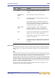
Safes
Each output channel (except return) has six types of output channel safes that each
each protects a specific control/area from the automation system.
The safes on the return channel are input channel types, of which there are only five
available (there is no dynamics).
You can only operate the safe switches via the channel strips (control surface and GUI),
which also provide on/off status information. The status of some of the safes is
displayed via LEDs in the output fast strips and master strips on the control surface.
For more information on what areas are protected by each safe, see Appendix
M "Parameters Protected By Safes" on page 469.
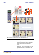
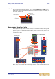
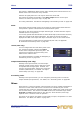
Insert (GUI only)
You can configure the send and return points of the
aux, matrix and master outputs in the insert
section of the configuration processing area. The
returns have a separate insert processing area,
which has the same function.
For routing information, see Table 25 “Navigating to
the Patching screen” on page 418.
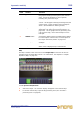
Output channel delay (GUI only)
Similarly to the input channels, all of the output
channels (except returns) have a delay that can be
incorporated into the signal path. However, this
can be a much larger delay, being in the range 0ms
to 500ms (milliseconds). For details, see “Input
channel delay (GUI only)” on page 284.
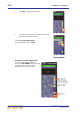
Processing order
Similarly to the input channels, you can change the processing order on all of the
output channels (except returns). For details, see “Processing order” on page 288.
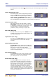
Mixes
Each of the aux, return and master output channels can send a variable contribution to
the mixes on each of the matrix buses. The buses are controlled in pairs via mix
controls that give continuous adjustment (in the range +6dB to off) of sub group levels
sent to matrix mixes. The controls in the mix section (mix and master bays) include
level/pan and level control knobs for each bus pair, whose function (auxes only)
depends on the current bus mode in operation.
The mixes on the outputs are similar in functionality to inputs, except there is no after
fader listen. For details, see “Mixes” on page 303.