
Operation Manual

610 Appendix P: Parameters Copied Through Scenes
PRO Series Live Audio Systems
Owner’s Manual
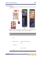
Gates
Not applicable.
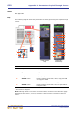
EQs
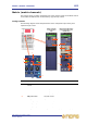
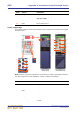
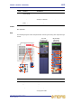
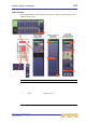
The following diagram shows the parameters of the EQ processing area copied through
scenes.
* Not shown in diagram.
Note: Although bands 1 and 6 are not shown above, the items in the table also apply.
Both bands have items 2, 3 and 4, and band 1 also has item 5 and band 6 also has
item 7.
Item Control Parameter
1 EQ switch EQ on/off
2 gain control knob EQ gain level
3 width control knob EQ width
4 freq control knob EQ frequency
5* SHAPE switch Band 1 shelving mode: bell, warm, high pass 6dB
or high pass 12dB
6 SHAPE switch Band 2 shelving mode: bell or high pass 24dB
7* SHAPE switch Band 6 shelving mode: bell, soft, low pass 6dB or
low pass 12dB
2
4
1
EQ processing
area in GUI
channel strip
3
2
5/6/7
4
3
2
4
3
2
3
2
3
4
4
6
master overview
in GUI channel
strip
1