XL8 Control Centre Quick Reference Guide Midas Klark Teknik Limited, Klark Industrial Park, Walter Nash Road, Kidderminster. Worcestershire. DY11 7HJ. England. Tel: +44 1562 741515 Fax: +44 1562 745371 Email: info@midasklarkteknik.com Website: www.midasconsoles.com XL8 Control Centre — Quick Reference Guide DOC04-XL8 Issue F — April 2010 © Red Chip Company Ltd. In line with the company’s policy of continual improvement, specifications and function may be subject to change without notice.
IMPORTANT SAFETY INSTRUCTIONS The lightning flash with arrowhead symbol within an equilateral triangle is intended to alert the user to the presence of uninsulated “dangerous voltage” within the product's enclosure that may be of sufficient magnitude to constitute a risk of electric shock to persons. The exclamation point within an equilateral triangle is intended to alert the user to the presence of important operating and maintenance (servicing) instructions in the literature accompanying the product.
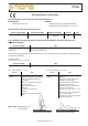
Midas EC-Declaration of Conformity The undersigned, representing the following manufacturer Manufacturer: Address: Midas Klark Teknik Ltd. Klark Industrial Park, Walter Nash Road, Kidderminster. Worcestershire. DY11 7HJ. hereby declares that the following product Product Type Number Product Description Nominal Voltage(s) Current Freq.
Licences The following are the license agreements applicable to the Midas Digital Equipment. End-User Licence Agreement for Midas™ and Klark Teknik™ Software IMPORTANT - Please read this document carefully before using this Midas™ or Klark Teknik™ Product. This is an agreement governing your use of software or other machine instructions already installed on this Midas™ or Klark Teknik™ Product, as well as other software that we provide for installation on this Product.
DATE INFORMATION. You understand that the Company may update or revise the Software but in so doing incurs no obligation to furnish such updates to you. However, the Company may in its discretion make updates available from time to time upon such terms and conditions as it shall determine.
and the Courts of England and Wales will have exclusive jurisdiction to hear and decide any dispute concerning it or its formation. No breach by you of any provision of this Licence shall be waived or discharged except with the express written consent of the Company and no failure or delay by the Company to exercise any of its rights under this Licence shall operate as a waiver thereof and no single or partial exercise of any such right shall prevent any other or further exercise of that or any other right.
xi Precautions Before installing, setting up or operating this equipment, make sure that you have read and fully understand all of this section and the “IMPORTANT SAFETY INSTRUCTIONS” at the front of this guide. This equipment is supplied by a mains voltage that can cause electric shock injury! The following must be observed in order to maintain safety and electromagnetic compatibility (EMC) performance. Safety warnings This equipment is fitted with two PowerCon® mains power sockets.
xii Handling the equipment Location Completely isolate the equipment electrically and disconnect all cables from the equipment before moving it. Ideally a cool area is preferred, away from power distribution equipment or other potential sources of interference. When lifting or moving the equipment, always take its size and weight into consideration. Use suitable lifting equipment or transporting gear, or sufficient additional personnel. Do not install the equipment in places of poor ventilation.
xiii Electric fields Safety equipment Caution: In accordance with Part 15 of the FCC Rules & Regulations, “… changes or modifications not expressly approved by the party responsible for compliance could void the user's authority to operate the equipment.” Never remove, for example, covers, housings or any other safety guards. Do not operate the equipment or any of its parts if safety guards are ineffective or their effectiveness has been reduced.
xiv XL8 Control Centre Quick Reference Guide
xv Contents Overview Chapter 1 Introduction . . . . . . . . . . . . . . . . . . . . . . . . . . . . . . . . . 1 About this guide . . . . . . . XL8 host software version Optional extras . . . . . . . Warranty and registration Service and support . . . . Chapter 2 . . . . . . . . . . . . . . . . . . . . . . . . . . . . . . . . . . . . . . . . . . . . . . . . . . . . . . . . . . . . . . . . . . . . . . . . . . . . . . . . . . . . . . . . . . . . . . . . . . . . . . . . . . . . . . . .
xvi Configuring the devices . . . . . . . . . . . . Configuring the XL8 with the snake type Setting up the I/O rack devices . . . . . . . How to patch . . . . . . . . . . . . . . . . . . . Chapter 8 . . . . . . . . . . . . . . . . . . . . . . . . . . . . . . . . . . . . . . . . . . . . . . . . . . . . . . . . . . . . . . . . . . . . . . . . . . . . . . . . . . . . .29 .30 .30 .31 Basic Operation . . . . . . . . . . . . . . . . . . . . . . . . . . . . .
Overview Volume 1: XL8 Control Centre Quick Reference Guide
1 Chapter 1: Introduction Welcome to the XL8 Control Centre. The XL8 Control Centre is a user-friendly, state-of-the-art, high performance digital console specifically designed for live use. The XL8 Control Centre, which forms an integral part of the XL8 Live Performance System, was conceived by Midas to offer audio professionals high-performance audio equipment, designed to provide no-compromise sonic quality with a feature set that offers all essential facilities and functions.
2 Chapter 1: Introduction Warranty and registration Midas has total confidence in the quality and reliability of this product. To back this up, this product comes with the standard Midas and Klark Teknik three year warranty. Please take the time to register your product by completing and returning the registration card or by registering on our website at www.midasconsoles.com. Service and support The XL8 is a very hi-tech piece of equipment.
3 Chapter 2: Introducing The XL8 Live Performance System The standard XL8 system offers 96 channel inputs, 51 outputs, 51 buses (32 auxes/groups, 16 matrices and three masters), 16 on-board effects processors, PEQs (four-band on inputs and six-band on outputs), up to 48 assignable GEQs (if all stereo effects units are being used), 16 configurable stereo effects (from eight options), surround panning (5.1, LCRS and quad) and comprehensive, easy-to-use routing.
4 Chapter 2: Introducing The XL8 Live Performance System • DL471 DSP (10-off): 1U 19” rack unit that forms part of the modular DSP engine. • DL461 Router (2-off): 3U 19” rack unit that provides the on-stage Cat 5e interconnectivity and the stage-toFOH link via a single ‘snake’, which can be copper cable or a fibre optic link. • Klark Teknik DN9331 RAPIDE (1-off): 6U 19” rack unit that is a motorised fader remote control for the onboard graphic EQs of the XL8. • Snakes and main cables etc.
5 Chapter 3: About The XL8 Control Centre This chapter introduces you to the XL8 Control Centre and provides a brief hardware description. Overview of the XL8 Control Centre The XL8 Control Centre comprises a combined control surface and graphical user interface (GUI) that provide an array of easy-to-use controls for the precise manipulation of audio.
6 Chapter 3: About The XL8 Control Centre Bay and GUI layout The XL8 control centre has five bays, of which there are three types: • Input bays — three input bays provide fast access to large numbers of faders and important input signal processing controls. The bays are numbered 1, 2 and 3, in order from left to right. • Mix bay — provides fast access to large numbers of creative mix faders.
7 XL8 control surface XL8 control surface During show time the screen functions that require fast access are controlled by control knobs (rotary encoders), pushbutton switches, faders etc. More complex functions that do not require this fast access are controlled by glide pad/trackball and navigational keys. An integral keyboard pulls out from underneath the output bay for text entry to enable setting up and configuration on the output bay GUI screen.
8 Chapter 3: About The XL8 Control Centre The choice of controls provided by each bay type are prioritised by access time importance. A fast zone area gives instant access to specific functions across the bay. A channel strip (to the right of the input and mix bays) gives greater control of the selected fast strip. Typically, the XL8 fast zone areas contain signal processing and routing levels for input bays, but only routing level control on the mix and output bay channel panels.
9 Front and rear connections The GUI, which forms a backdrop to the control surface, represents pictorially the layout of the control surface so that its displays are easy to follow at a glance. Not only does it reflect what is happening on the control surface, but it also provides extra functionality via a GUI menu.
10 Chapter 3: About The XL8 Control Centre Pull-out keyboard The XL8 has a QWERTY keyboard that is used mainly for inputting text, such as when configuring a channel or using automation. It is fitted on a sliding tray underneath the output bay (see Figure 4 “Front and rear connectors on XL8 Control Centre” on page 9) and only operates the output bay GUI screen.
Volume 2: XL8 Control Centre Quick Reference Guide Operation
13 Chapter 4: Before You Start This chapter provides useful background information on XL8 operation. While this system is a complex, high-tech piece of equipment, we have made it as easy to use and as user-friendly as possible. Principles of operation XL8 Control Centre operation is based on the concept of colours and groups rather than ‘layering’ or ‘paging’, which is the case with most digital consoles on the market today.
14 Chapter 4: Before You Start Although the state of the control centre is copied every five seconds, it is not stored in a scene. Instead, it is placed in the NVRAM (non-volatile random access memory) of the control centre’s memory, which is a type of RAM that doesn't lose its data when the power goes off. If the control centre loses power accidentally, these settings are loaded so that audio parameters are identical, thus avoiding audio level jumps.
15 Chapter 5: Working With The XL8 Control Centre Although many controls on the XL8 Control Centre are similar to their equivalent analogue-type counterparts, some have been specifically designed for the XL8, particularly those for navigation and GUI operation. As you will probably have had experience on analogue consoles, you will already be familiar with most of the XL8 controls and their operation. Therefore, this chapter only deals with the GUI controls that may be new to you.
16 Chapter 5: Working With The XL8 Control Centre Click Moving the pointer to a specific point of the GUI screen and then pressing the left button is called “clicking”. This is fundamental to GUI operation and forms the basis of many of its operations, such as switching a button on/off, selecting list and menu items, text editing etc. Doing the same with the right button is called “right-clicking”.
17 Using the GUI menu About windows There are three main types of window you will encounter when using the GUI: • Properties windows contain elements that you can select or edit, such as options, lists, tick boxes, text fields etc. • Message windows contain text that can be a prompt or an error message. Generally, this type of window will contain a user-editable text field and OK and CANCEL buttons.
18 Chapter 5: Working With The XL8 Control Centre Opening a GUI menu screen via the control surface You can open some of the GUI menu screens by using the buttons in the screen access section of the primary navigation zone. Each button provides direct access to two screens, as indicated by the adjacent text to its right. Press the button to open the first screen mentioned, and press it again to open the other one.
19 Chapter 6: Navigation This chapter introduces you to XL8 navigation and shows you how to use the navigational tools of the XL8 Control Centre. You can also use the GUI to assist in navigation. For information, refer to the XL8 Live Performance System Owner’s Manual (part number DOC02-XL8). For information on navigating the scenes in automation, see “Managing the scenes” on page 48.
20 Chapter 6: Navigation How the output channels are managed All output channels, except masters, are paired and managed in banks of 16 (eight pairs per bank). The mix and output bays have eight dual-channel fast strips each. The ones in the mix bay are for auxes (32) and returns (16), and the ones in the output bay are for matrices (16). The output bay also houses the thee master channels (two stereos and a mono). Both bays use the channel strip in the mix bay.
21 Location of the navigational controls Location of the navigational controls This section shows the position of the control surface navigational controls per bay. 1 1 1 3 1 1 1 1 5 1 1 3 Input bay 1 Key: 1 Quick access button 2 LCD select button 3 Scroll buttons 4 Numeric keypad 5 LED indicators — show which bank of inputs is currently selected. When a group is selected, an LED will flash if its bank contains a group member that is not currently at the control surface.
22 Chapter 6: Navigation 1 2 3 3 1 Input channel strip 4 Key: 1 Scroll buttons 2 Aux and matrix mix select buttons 3 Control knob provides navigational information, whereby its backlight colour changes to suit the currently selected pair, matching those in the mix section (shown above) 4 LCD display shows the currently selected mix pair (aux or matrix); mtx legends illuminate when mix pair are matrices and extinguish when they are auxes Input fast strip Figure 8: Input bay navigational contro
23 Location of the navigational controls 1 1 2 1 1 1 1 Mix bay 3 1 Key: 1 Quick access button 2 LCD select button 3 Scroll buttons 1 4 Output channel select buttons (returns and auxes) 5 LED indicators — show currently selected bank of outputs (returns, auxes or matrices) 4 3 5 Figure 9: Mix bay navigational controls XL8 Control Centre Quick Reference Guide
24 Chapter 6: Navigation 2 2 1 1 1 1 1 Output bay Key: 1 Quick access button 2 LCD select buttons Figure 10: Output bay navigational controls About GUI navigation While the control surface provides instant, one-button access to many controls, the GUI provides an alternative way of navigating the XL8 and offers some unique methods of its own.
25 How to navigate >> To find a GUI screen that you recently opened Use the back/forward browser buttons to do one of the following: • To return to the GUI screen you just opened, click the back button (as shown right). • To open one of the GUI screens you have recently visited, click the back/forward buttons. The back button will take you back through your browser history, while the forward button goes the opposite way.
26 Chapter 6: Navigation Selecting channels, mix buses and groups There are a number of ways you can select a channel/mix bus from those currently populating the control surface, particularly by using the quick access buttons and LCD buttons. >> To select an input channel Press its LCD select button or any of its quick access buttons. >> To select an output channel In the mix or output bay, do one of the following: • To select the left channel of the pair, press its LCD select button.
27 Chapter 7: Patching This chapter describes the patching function of the XL8. Introduction The patching function is fundamental to XL8 operation as, until the I/Os have been correctly patched, you won’t get any audio. Patching is done entirely at the Patching screen, which is an option in the GUI menu.
28 Chapter 7: Patching Item Description 6 Status bar that shows the patching status of the inputs and outputs as a percentage. 7 A pictorial representation of a physical device. Patching screen function buttons The function panel buttons of the Patching screen are described in the following table. When a button is selected, its background colour changes to a lighter shade. Legend Description SINGLE Lets you patch a single source to a single destination or multiple destinations.
29 About the patching procedure About the patching procedure Although patching can be thought of as routing/rerouting the console’s incoming, internal and outgoing signals, in the context of the Patching screen, patching also encompasses the setting up and configuration of the devices.
30 Chapter 7: Patching 3 In a channel, configure its parameters. For example, in channel “In1” adjust the gain and switch on the +48V phantom voltage (shown right). Repeat for the other channels in the card as necessary. 4 Repeat step 2 and step 3 for the other cards as necessary. 5 If necessary repeat step 1 to step 4 for any other devices of the same type. 6 Click OK. Configuring the XL8 with the snake type Important: The XL8 must be configured with the correct snake type before operation.
31 How to patch 4 In the device ID: drop-down list, click the ID you want for the device. For example, choose “ID3”. 5 In the device options: drop-down list(s), choose the type of each card fitted in the physical unit. For example, choose “Analogue 8 Input”. Repeat for any other cards. 6 Click OK. How to patch Patching, basically, involves selecting the source patching connectors in the From section of the Patching screen and then selecting their destination(s) in the To section.
32 Chapter 7: Patching Single patching (SINGLE) The SINGLE function button allows you to patch a single source to a single destination or multiple destinations. >> To patch a single source to a single destination The following example shows you how to patch an output from a mic splitter to an input channel. 1 Click SINGLE. 2 In the From section, click the source patch connector. For example, choose the first patch connector of a mic splitter.
33 Chapter 8: Basic Operation This chapter is intended to familiarise you with the XL8 Control Centre by showing you how to carry out some basic operations in order to get some audio out of it. Note: The following input bay operations can be carried out at any input bay. Setting a mic amplifier’s input gain The XL8 Control Centre has two input gains per channel, one is the remote gain for the analogue mic pre (stage box gain) and the other is the digital trim (console gain).
34 Chapter 8: Basic Operation 2 Press the left/right arrowed gain swap button. This swaps console digital trim to stage box input gain (and vice versa). The diagram right shows the two types of gain that can appear in the input gain/trim section at the top of each GUI input fast strip. 3 Adjust the gain trim control knob to set the stage box input gain (2.5dB steps for the DL431 Mic Splitter and DL443 Analogue Jack I/O Module, and 5dB steps for the DL451 and DL351 Modular I/Os).
35 Input equalisation (E zone) Input equalisation (E zone) Use EQ to equalise the input signal via the treble, hi-mid, lo-mid and bass filters, which are in the input channel strip’s E zone. Treble and bass each have a parametric filter option with three specific shelving modes. Visual feedback for EQ is via GUI screen only, which also has a graphical representation of the filter.
36 Chapter 8: Basic Operation Input dynamics processing (D zone) This section deals with assigning compressor and gate dynamics processors using the controls in the input channel strip’s D zone. There are four compressors available — corrective, adaptive, creative and vintage — each with the option of hard knee, medium knee and soft knee.
Output processing 5 37 Press MODE to try the different compressor types (Corrective, Adaptive, Creative and Vintage). For example, Creative shown right. >> To set up a gate 1 In the desired input fast strip, press ON in the gate section to switch the gate in. 2 Do one of the following to select the channel and assign the gate detail area to the GUI channel strip: 3 • In the gate section of the desired input fast strip, press the quick access button.
38 Chapter 8: Basic Operation Using VCA/POP groups VCA/POP groups allow simultaneous control over a number of channels. Being instantly recognisable, they provide a quick method of bringing particular channels to the control surface and save you having to remember their name/number. You can choose channel group associations and also configure the colour and legend of each group’s LCD select button, which is used for group member assignment and recall.
39 Using VCA/POP groups Configuring VCA/POP groups The default name and associated colour of a group, as shown on its LCD select button and on the GUI, can be configured to suit your own preference. You can also globally change the colour of a group’s members to match its own colour. Configuration is done via the Group Sheet screen (shown below).
40 Chapter 8: Basic Operation Setting up a mix XL8 has 32 configurable mix buses, each of which can be aux mixes, subgroups and mix minus. The aux mixes can also be set up as stereo pairs or mono. 16 matrix outputs can also be accessed directly from input channels via level controls, which gives the XL8 the ability to provide 48 discrete mixes, plus left, right and mono.
41 Setting up a mix Any pair of 48 mix buses can be locked onto the control surface of the input bays on an individual channel-by-channel basis, so that the two most crucial auxes for each channel (most pertinent effects auxes, main artistes’ foldback, etc.) can be available at all times. For more information, see “Programming the mix preset” on page 43. >> To select the mix bus mode 1 In the mix bay, select the aux you want.
42 Chapter 8: Basic Operation Selecting the type of mix In addition to the mono, group and mix minus types of mix, you can also have a stereo aux mix. This is set up in the same way as for a mono aux mix, but the channels must be linked first. For information on selecting and setting up mixes, see “Setting up a mix” on page 40 How the different mixes are shown on the GUI The input bay GUI screens indicate at a glance which type of mix is in operation.
Setting up a mix 43 The linked parameters default to the user-configurable global default link settings, which are set via the GUI menu (choose home Preferences Linking). However, you can override these default link settings for the pair via the Stereo Linking Options window (shown right), which is opened by clicking the st. linking options button (GUI channel strip). In stereo mix mode the top control knob becomes pan adjust and the bottom one adjusts level.
44 Chapter 8: Basic Operation Fader flip Fader flip is a GUI-only function that changes input fader control. By selecting fader flip, the input bay faders control the level of the selected aux send’s contributions to the bus master, instead of controlling the input levels. >> To switch fader flip on and off At a GUI screen, choose home Preferences General. Then, select the Fader Flip option (see “Changing the user interface preferences” on page 230).
Setting up the effects rack 45 Stereo Graphic EQ — basically, two versions of the internal GEQ of the XL8, but with the addition of a LINK switch. When both GEQs are linked together, their faders move a corresponding amount from the positions they were in when initially linked. So, although their adjustment will be equal, their dB values may be different. When unlinked, the GEQs are independent of each other.
46 Chapter 8: Basic Operation 3 In the effect’s (empty) window, click Change Device Type. 4 In the Change Device Type window, choose the device type. For example, “Phaser”. 5 Click OK. 4 5 6 Change the parameters of the new effect device as necessary. For example, adjust control knobs, press buttons etc. You can even change the effect’s name by editing its name field (upper-left corner of effect window).
Automation 47 Automation XL8 automation is managed from the Automation screen of the GUI menu, with support from the automation section of the control surface (output bay). The Automation screen (a typical example is shown right) has the following functions and features: • Show management — see “Managing the shows” on page 47. • Scene management — see “Managing the scenes” on page 48. • Event management — see “Additional control — managing events” on page 50.
48 Chapter 8: Basic Operation >> To create a new show 1 Click NEW. 2 At the Enter new show name: message window, type your chosen name for the new show. 3 Click OK. You can now create and manage the scenes for your new show. >> To save a show or create a new one from the current settings Do one of the following: • To update the current show with the latest settings, click SAVE. • To create a new show using the current show settings, click SAVE AS.
49 Automation The automation section in the output bay (see item J in Figure 2 “Main areas of control surface” on page 7) supports the Automation screen by providing controls for scene navigation, selection and management. The jogwheel is a unique automation controls, whereas the other buttons are replicated on the GUI. >> To navigate the scenes/point scenes Rotate the jogwheel. Individual scenes/point scenes are scrolled forwards/backwards, wrapping back to the beginning/end of the show.
50 Chapter 8: Basic Operation Additional control — managing events You can create crossfades and you can use the MIDI or GPIO functions of the XL8 to control the parameters of an external device (outgoing) — and conversely you can use an external device to control the XL8 (incoming). Also, by using the XL8’s unique ‘internal’ event option, you can trigger events from within the showfile itself. All this is done by creating events in scenes/point scenes.
Configuring the inputs and outputs 51 Show editor The show editor is a GUI-only function that allows you to very easily copy and paste settings through scenes. This is done via the Show Editor screen. The Scenelist on the right of the screen is a cue list of the current show. Source lists (channels, GEQs, effects and groups) are to the left of the screen, from which you can copy the settings, and in the middle (Sections) are the areas you can copy.
52 Chapter 8: Basic Operation Using copy and paste The copy and paste buttons (upper-right corner of GUI) let you copy the parameters of a channel’s detail area (EQ, compressor, gate etc.) or all of its details areas, and paste them to another channel/all channels of a similar type. Both buttons have a right-click menu. >> To copy a detail area to a channel/all channels 1 Navigate the detail area to its local channel strip (see “Selecting a detail area” on page 26). 2 Click copy.
User library (presets) 53 User library (presets) The XL8 has a user library where you can store settings, such as for the EQ or even the whole channel. For example, you may wish to store the EQ settings of a singer who may be called upon to perform during a future show. You can then easily recall these EQ settings to the appropriate channel when required. The settings are stored as presets, which are saved in a library. The library files are managed via a Preset Manager screen in the GUI menu.
54 Chapter 8: Basic Operation Surround panning In addition to stereo and left-centreright (LCR) panning, XL8 has three surround panning modes: quad; left, centre, right and surround (LCRS); and 5.1 surround. To help you visualise the surround panning envelope, the masters detail area of the GUI channel strip has a spatial diagram (shown right) that updates when you operate the panning controls. L C R Position cursor Sound image Speaker The 5.
55 Two-man operation Two-man operation The XL8 Control Centre can be operated by two people simultaneously. To do this one or two of the input bays are designated as area B. Initially, all input bays are area A, but after they have been designated as area B, both areas operate independently of each other. This feature can also be used by a single operator if they require somewhere to store important channels.
56 Chapter 8: Basic Operation Saving your show files to a USB memory stick When you are satisfied that your show file is how you want it, we recommend that you save it to a removable storage device (USB memory stick). This provides a valuable back up should the show file stored in the internal memory of the XL8 be lost, for example, due to inadvertent deletion. You can also load show files onto the XL8 from the same storage device.
57 External AES50 synchronisation External AES50 synchronisation If you want to connect AES50 audio between two Midas digital consoles the slave console must be set to external AES50 synchronisation, irrespective of the synchronisation source of the master console.
58 Chapter 8: Basic Operation XL8 Control Centre Quick Reference Guide
Volume 3: Connecting And Setting Up The System XL8 Control Centre Quick Reference Guide
61 Chapter 9: Setting Up The System This chapter shows you how to set up an XL8 Live Performance System to its default configuration. Note: If you want to set up the XL8 Live Performance System using a configuration other than the default, please contact Midas Technical Support for details. Initial set-up procedure Initial system set-up basically comprises: • Unpacking and checking the equipment — see “Unpacking the equipment” below. • Making up the racks — see “Making up the racks” below.
62 Chapter 9: Setting Up The System Wiring instructions This section gives the system cabling details for the XL8-specific equipment and, although it is laid out in recommended order, this order is not critical. When making the connections, please make sure they match those in “XL8 system interconnections” on page 64. >> To connect both routers together Important: Without this connection system snake redundancy will be compromised.
63 Wiring instructions >> To connect the XL8 to the RAPIDE Connect one of the eight ETHERNET (EtherCon® XLR) sockets on the rear of the RAPIDE unit to the Ethernet control 1 socket of the active network (X or Y) on the rear of the XL8 Control Centre (see “XL8 system interconnections” on page 64).
64 Chapter 9: Setting Up The System XL8 system interconnections This diagram shows the network interconnections for a typical FOH XL8 system. Rear of FOH XL8 Control Centre RAPIDE Connect to both X and Y networks Note: All connections are dual redundant, so the system can operate quite normally using either the X or Y cables. 1 1 8 7 6 5 4 3 2 1 2 2 8 7 6 5 4 3 2 1 Stage rack 1 A X ID: 1 Inputs: 1 - 24 IP: 192.168.32.1 1 1 A ID: 2 Inputs: 25 - 48 IP: 192.168.32.
65 XL8 system interconnections FOH rack Note: For connections specific to the 19” rack units, please refer to their respective operator manuals B ID: 1 Config: I/O/D IP: 192.168.36.1 1 1 B Caution! Don’t forget the interconnection between the two routers, as system snake redundancy will be compromised without it. ID: 2 Config: I/O/D IP: 192.168.36.
66 Chapter 9: Setting Up The System Powering the XL8 system The following details the recommended power up and power down procedures for the XL8 system. >> To power up the XL8 system Important Note: DO NOT switch on the speaker sub-system until after the start-up of the XL8 system has been completed.
67 Switching the XL8 Control Centre on/off Switching the XL8 Control Centre on/off Carry out the following to switch the XL8 Control Centre on/off in a safe manner, observing all WARNINGS and Cautions. >> To switch on the XL8 Control Centre WARNING! DO NOT INSERT OR REMOVE A POWERCON® CONNECTOR INTO/FROM REAR OF CONTROL CENTRE WITH MAINS POWER AND ANY OF THE MAINS BAY SWITCHES ON. YOU MUST MAKE SURE ALL MAINS BAY SWITCHES ARE OFF AND MAINS IS SWITCHED OFF AT THE POWER OUTLET(S) FIRST.
68 Chapter 9: Setting Up The System >> To switch off the XL8 Control Centre 1 Make sure you have saved any shows, scenes or settings you require (see “Saving your show files to a USB memory stick” on page 56). 2 At the GUI, choose home Preferences Shutdown System. 3 At the Shutdown ENTIRE system? prompt, click OK. This initiates the shutdown down sequence. During the shutdown sequence the GUI screens will shutdown and all of the LCD select buttons on the control surface will turn red.
Volume 4: Appendices XL8 Control Centre Quick Reference Guide
71 Appendix A: Troubleshooting This chapter gives a brief troubleshooting guide to the XL8 Control Centre. No audio If you have set up the XL8 and followed all of the instructions for obtaining audio, but you are not hearing anything through the speakers, check the following: • Make sure the appropriate ST buttons in the channel fast strips are on. • Make sure the appropriate ST buttons in the source a/b panels (monitors section of the output bay) are on. • Make sure nothing is muted.
72 Appendix A: Troubleshooting >> To open the Diagnostics screen At a GUI screen, choose home Diagnostics. >> To open the X or Y network tab sheets In the Diagnostics screen, click the tab title (X Network or Y Network) of the network you want. About the Diagnostics Inspector window Clicking an item will open its Diagnostics Inspector window (shown right), which provides you with detailed information, particularly if it has an error condition.
Thank you for reading through this Quick Reference Guide. We hope you found it useful. Please feel free to send us your comments. More detailed information on the XL8 can be found in the XL8 Live Performance System Owner’s Manual (part number DOC02-XL8). This is available for download from our website. Our contact details and website address can be found at the front of this document.
© 2010 Red Chip Company Ltd. Midas Klark Teknik Limited Klark Industrial Park, Walter Nash Road, Kidderminster. Worcestershire. DY11 7HJ. England. Tel: +44 1562 741515, Fax: +44 1562 745371 Email: info@midasklarkteknik.com Website: www.midasconsoles.