
User guide

flame length has been set wide open for average
conditions. Decrease the combustion air if a longer,
softer flame is desired.
12. Check the operation of the burner; start and stop it
several times with the thermostat or operating
control.
13. With the burner running, check the operation of all
limit and associated controls.
14. PERFORM THE FOLLOWING FINAL ADJUSTMENTS
for combustion and flue gas temperature. Take the
flue gas samples and temperature immediately
ahead of the draft control.
A. The flue gas temperature should be above
325¡F but not exceeding 550¡F. Excessive flue
gas temperatures will result in low efficiencies.
Low flue gas temperature may cause excessive
condensation. Reset gas input if necessary to
adjust stack temperature.
B. Make the final setting of the combustion air
shutter by checking the flue gases with an
ORSAT or similar combustion testing
instrument. The carbon monoxide content
should conform to local codes, or in their
absence, to the level specified in the United
States or Canadian Standard referenced on the
front cover of this manual; and the carbon
dioxide content should be approximately 9.5%
for NATURAL and 12.1% for PROPANE, or
within the limits prescribed by local codes.
15. Check the draft control to make sure there is no
spillage of flue products into the room.
16. FILL OUT THE INSTALLATION ADJUSTMENT
DATA TAG and affix to the burner or gas utilization
equipment.
NOTE: For subsequent normal starting and shut off
procedure, refer to CONSUMER INSTRUCTIONS or to
the instruction plate mounted on the burner.
PART 2 SERVICE
CONSUMER CAUTION: Do not tamper with the
unit or controls. If trouble occurs, contact a qualified
Service Technician.
DANGER: Be sure that the Main and Pilot Manual
Shut-Off Valves, Combination Valve and Burner
Power Switch are turned OFF before removing any
parts for service.
WARNING: All cover plates, enclosed and guards
must be in place at all times except during
maintenance and servicing.
IX PILOT
The pilot is of the premix, blast type. The full force of
blower air is brought into the mixing tube where the
proper amount of gas is added through the pilot orifice.
This mixture is discharged through the pilot which
contains a perforated flame retention plate. The outer
holes diverge to spray the mixture against the side wall
of the pilot tip to provide flame retention. The mixture
through the center port provides the flame that contacts
the flame detection rod and also ignited the main gas.
■■ Surrounding the base of the pilot flame is a conical
shroud which protects the flame against extraneous air
currents and inhibits "blow-off" from an overly rich flame.
■■ The pilot gas orifice is the same size both for
NATURAL and PROPANE gas, consequently the gas
pressure required for PROPANE is lower than that
required for NATURAL gas.
CAUTION: Do not indiscriminately increase pilot
orifice size. Pilot troubles are rarely cured in this
manner and new troubles may be created.
■■ Under normal conditions, with a slight negative
pressure in the combustion chamber, pilot operating
pressures are 3.5" W.C. NATURAL gas and 2.25" W.C.
PROPANE.
■■ Some conditions which may require a change from the
normal settings include: extremely long tubing
connections between the regulator and pilot solenoid,
high negative or positive combustion chamber pressure,
actual air shutter setting and altitude extremes.
■■ Do not subject the Pilot Solenoid or Pilot Regulator to
an inlet pressure over 14.0" W.C. See section VII PIPING
for high pressure gas. Note that the standard pilot
pressure regulator is not a tight shut-off and, during
standby, the outlet pressure will build up to the full inlet
pressure.
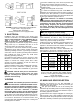
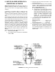
■■ The spark rod is located on the center line of the pilot
and is positioned so the high tension voltage will arc to
the inside of the center port of the retention plate (see
Figure 7).
■■ The flame rod must be positioned as shown in Figure
7 so that the electronic control will detect a proper flame.
Note that it is slightly above the centerline of the pilot.
■■ Both the spark and flame rods are current carrying
conductors and, along with their connecting wires, must
be kept free of contact with conductive metal parts of the
burner. Rod insulators and wire insulators should be
clean, dry and free of cracks.
■■ Rods are made from heat resistant alloys and can be
expected to have a long service life. They should be
routinely inspected, however, for corrosion or loss of
metal.
■■ The pilot air tube must be kept free of kinks or inside
obstructions and its inlet end must be positioned per
Figure 7, otherwise air flow could be reduced sufficiently
and adversely affect the pilot flame.
TABLE 4 Pilot Specifications
-6-
PILOT GAS
PRESSURE
ORIFICE
DIAMETER
APPROX.
CAPACITY
NOMINAL BTU/Cu. Ft.
NATURAL-1000 PROPANE-2500
2.5"-4.0" W.C. 2.25"-3.5" W.C.
#68 WIRE DRILL
.031 DIA.
2500