
Owner manual


TROUBLE CHART
Make sure the switch or timer is calling for heat. Defective wiring or loose connections can simulate the component
defects outlined below. Check associated wiring before replacing a component.
ELECTRICAL AND FLAME CHECKS MUST BE MADE IN THE ORDER LISTED.
I. MOTOR WILL NOT RUN.
A . Confirm 120 volts between strip terminals.
1. L2 and L1: No voltage, Fused Disconnect off or
Fuse open.
2. L2 and 3: No voltage, Safety Controls open.
3. L2 and 10: No voltage, Burner Switch or
Timer open and/or Remote Switch or Timer
open.
4. L2 and 4: No voltage, optional high or low gas
pressure switch is tripped.
5. L2 and Thermal Switch Terminal 1 (black wire):
a.No voltage, Thermal Switch is defective.
b.Voltage present, defective Motor.
II. MOTOR RUNS CONTINUOUSLY, BUT NO FLAME
AND BURNER HOUSING COOL.
A. Make certain Flame Safeguard lockout switch is
not tripped.
CAUTION: Tests are valid only during the 4 or
10 second trial for ignition. Main Manual Shut-Off
Valve must be closed and Manual Ignitor Valve
open.
1. Confirm 120 volts on strip terminals L2 and 5.
a.Voltage present: Continue to Step 2.
b.No voltage:
J81A - Motor Interlock Switch defective.
J121A - Blower Air Switch defective.
2. Confirm 120 volts between strip terminal L2 and
terminal 6.
a.Voltage present, continue to Step 3.
b.No voltage, Flame Safeguard defective.
3. Confirm 120 volts on strip terminal L2 and 7.
a.Voltage present, continue to Step 4.
b.No voltage, Flame Safeguard defective.
4. Check for ignition spark (spark length
approximately 1/8").
a.Between spark generator hi-voltage terminal
and ground: No spark, defective Spark
Generator.
b.Between spark electrode wire and chassis
ground: No spark, Spark Generator defective.
c.For checking spark gap between Spark
Electrode and Ground Barrier, refer to PART
2 SERVICE VIII IGNITOR AND
REGULATOR ASSEMBLY, SPARK TEST.
5. Connect manometer to ignitor gas pressure
test tap, and check pressure during trial for
ignition period.
a.No pressure, confirm that pressure of at least
5.5" W.C. is available at the inlet of the Ignitor
Gas Valve, and repeat Step 5. If still no
ignitor gas pressure, ignitor gas valve defective.
b.Ignitor gas pressure 3.0" to 4.0" W.C.,
continue with Step 6.
c.Adjust the ignitor regulator to 3.5" W.C. while
gas is flowing.
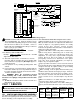
6. Open the charging door, make sure any door
open interlock is temporarily by-passed and
repeat trial for ignition.
a.Open Main Manual Shut-Off Valve. With main flame
present, close charging door, remove temporary door
open interlock and check incineration chamber
pressure. Burner peep hole can be used for access
to obtain approximate reading (See Figure 3). Make
sure sensing tube extends into the incineration
chamber at least 6". Pressure should be between
0" to minus 0.5" W.C. for J81A, 0" to minus 1.0" W.C.
for J121A. If pressure is on the high negative side of
the range, increase the ignitor flame gas pressure to
4.0" to 5.0" W.C.
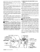
b.No flame present, clean and reset electrode
assembly per Figure 5 and repeat Step 6a.
III. IGNITOR FLAME ON ONLY DURING THE 4 or 10
SECOND TRIAL FOR IGNITION.
A. With motor running, confirm 120 volts as follows:
1. Between strip terminals L1 and L2: 120 volts
present, voltage OK.
2. Between strip terminals L1 and Ground: 120
volts present, ground OK.
3. Between strip terminals L2 and Ground: No
voltage, neutral OK.
B. Follow test procedure as specified in Step II.A.
1. Disconnect Flame Electrode Wire and check
for continuity.
2. Connect DC voltmeter in test jack in amplifier.
With ignitor flame on, reading should be at 2 or
more volts DC and steady. Adjust ignitor gas
pressure to obtain acceptable signal and note
gas pressure and signal strength for future
reference.
C. If all checks listed above were satisfactory and
the ignitor will not stay lit, Flame Safeguard defective.
IV. IGNITOR LIGHTS BUT NO MAIN FLAME.
A. Confirm 120 volts between strip terminal L2 and 8.
1.120 volts present, continue with Step B.
2.No voltage, Flame Safeguard defective.
B. Connect manometer to Main Automatic Valve
downstream pressure tap.
1. No gas pressure when valve is energized.
a.Confirm that pressure of at least 5.5" W.C.
NATURAL, 8.0" W.C. PROPANE, is available
at the inlet of the Main Automatic Valve.
b.Pressure at inlet side OK, Main Automatic
Valve defective.
V. SHORT MAIN FLAME.
A. Low gas pressure.
B. Air shutter open too far.
C. Input adjuster not set properly.
VI. LONG HAZY MAIN FLAME.
A. High gas pressure.
B. Air shutter closed too far.
C. Insufficient free air in incineration chamber.
D. Dirty blower wheel.
E. Input adjustor open too far for air shutter setting.
VII. GAS FAILS TO SHUT OFF.
A. Main Automatic and/or Ignitor Gas Valve defective.
B. High gas pressure.
-10-