
Manual


and weight of the material employed to maintain clearance and prevent physical damage
and separation of joints.
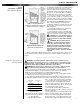
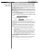
?? A draft hood or barometric draft regulator shall be installed in the same room or enclo-
sure as the equipment in such a manner as to prevent any difference in the pressure
between the hood or regulator and the combustion air supply. In no case shall the relief
opening of the draft hood or barometric draft regulator be located at a point lower than the
top of the highest flue passage in the equipment.
_____________________________________
CAUTION: Do not add any power consuming devices in the low voltage circuit
as overloading of the transformer can result. Do not use Motor Relay to operate any
external devices as overloading of motor relay contacts can result.
Note: If any of the original wiring as supplied with the conversion burner must be replaced,
it must be replaced with type TFF wire or its equivalent.
Installation wiring and grounding of the burner must conform to local codes, or in their
absence in the United States to National Electric Code, ANSI/NFPA No. 70-latest
edition; in Canada, to Canadian Electrical Code Part 1, CSA Standard C22.1.
?? Use 14 gauge copper wire for line voltage wiring. Be sure to hook up to a permanently
live circuit. Provide a fused on-off disconnect switch carrying a minimum 3 amp fuse.
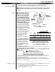
?? The frame of the burner must be well grounded. A terminal is provided in the control
box for positive grounding where insulated pipe couplings are used or where any doubt
exists regarding grounding sufficiency.
?? Confirm that the polarity is correct—hot wire to black wire, neutral to white, and that
the neutral line is not subject to induced low voltage (check white wire to earth ground)
from other equipment as that can cause the electronic flame safeguard to malfunction.
?? Each installation must include suitable limit controls. Existing oil burner combination
limit and operating controls are normally NOT SUITABLE for gas burner use.
V Electrical
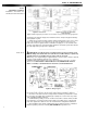
Figure 3: Draft Hoods Figure 4: Location for Barometric
Draft Regulator
Figures 3 and 4: Copyright by the American Gas Association. Used by permission of the copyright holder.
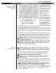
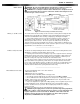
Figure 5: Wiring Diagram
4
Part 1 Installation
IV Chimney, Vent Connector,
and Draft Control Continued
Part 1
Installation Continued