
Manual

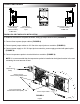
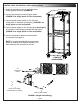


1. Install fan controller to fan panel as shown, using (2) Phillips head screws. (FIGURE A)
2. Connect fans to power jumper cables. (FIGURE A)
3. Connect power jumper cables to 12V fan drive output jacks on controller. (FIGURE A)
4. Connect power supply to 12V 2A input jack on controller, power supply provided with panel option.
(FIGURE A)
5. Connect temperature probe to terminal block on controller. (FIGURE A)
NOTE: It is recommended that the temperature probe be installed at the highest location in the rack
containing the most amount of heat.
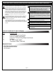
CONNECTIONS DIAGRAM
FANPNL-2DC OR IFANPNL-2DC INSTALLATION
(From Power Supply
Provided With Panel Option)
Screws (2) 5/16”
Thread Cutting Phillips Head
FIGURE A
Page 5
12V Fan Drive Outputs (2)
(Center Positive)
2.5MM Jack
The mi s to r
Fa n D r iv e
Ou tpu t
12V @ 2 A
Input
+
_
Co m pa r at or
Ci r cuit
No us er ser viceable
pa r ts in sid e
+
_
Temperature
Probe (Thermistor)
Input
12V 2A Input From
Power Supply
(Center Positive)
2.5MM Jack
(To
Temperature
Probe)
Power Jumper Cable