
Owner manual


12
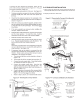
ATTACHING THE POINT OF SALE CABLE
Remove the cable (P/N 59198) from the Kit. Attach the 90
degree plug to the rear of the touchscreen display and route
the serial connector out the grommetted bottom hole and along
the gas pipe. Connect the serial connector with the cable sup-
plied by the customer.
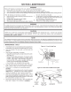
CONVEYOR BELT REVERSAL
Conveyor belt reversal consists of three steps:
1. Physically reversing the conveyor belt
2. Resetting direction jumper on the conveyor control board.
3. Switching the photo detector.
REVERSING THE CONVEYOR BELT
Remove the conveyor from the oven and nd the master link
location. Remove master links and remove the belt from the
conveyor frame. Reassemble the belt back onto the frame (in
the reverse direction) and reinstall the master links. Replace
the conveyor assembly in the oven.
RESETTING DIRECTION JUMPER
Locate Jumper P1 on the conveyor control board. Move jumper
from terminals 1 and 2, and replace onto terminals 2 and 3.
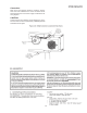
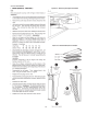
SWITCHING PHOTO DETECTOR
Remove both rear fan belt covers, then remove the motor
cover assembly from both sides of the oven. The photo eye is
located on the front side of the left motor bracket. Disconnect
the three connecting wires, noting which color wires assemble
to the associated wires on the photo-detector. Remove the
entire photo detector bracket. Replace the assembly to the
right-hand side of the unit, mirroring the way it was assembled
on the left. Reconnect the detector wiring in the same order
it was on the left.
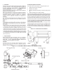
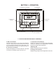
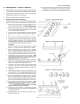
Incoming electrical power lines are fed through the strain-relief
tting, shown in Figure 2-12. The electrical supply connections
are made inside the electrical junction box. The power lines
then connect to the oven circuits through safety switches
located inside the machinery compartment and each blower
motor compartment. These switches interrupt electrical power
to the oven when the Machinery Compartment Access Panel
is opened, OR when either of the blower or rear shrouds is
removed.
Mount the new reector bracket to the provided holes on the
front right-hand side of the oven. The reector should be po-
sitioned just above the conveyor belt.
Using an assistant, hold both back cover switches in the closed
position. This will allow power to the photo-eye, and it will pro-
vide a red beam for aiming. Loosen one of the screws holding
the photo detector gimbal tight, allowing it to be reaimed at
the reector. The beam should hit exactly in the center of the
reector, then tighten the screw back down.
Note: This is MUCH easier in reduced light.
Replace all covers.