PS536GS Gas Domestic, Std. Export & CE ENGLISH/French/Spanish P/N 50236 November 18, 2008 Rev.E Price $30.00 PS536GS Gas Ovens Models: Combinations: • • • • PS536GS Gas Single Oven Double Oven (Two-Stack) Triple Oven (Three-Stack) OWNER'S OPERATING, INSTALLATION, AND PARTS MANUAL for domestic, standard export and CE export ovens © 2003 Middleby Marshall, Inc. is a registered trademark of Middleby Marshall, Inc. All rights reserved.
NOTICE: This Owner's Operating and Installation Manual should be given to the user. The operator of the oven should be familiar with the functions and operation of the oven. This manual must be kept in a prominent, easily reachable location near the oven. ENGLISH Ovens are shipped from the factory configured for use with natural gas. If permitted by local, national and international codes, at the time of installation the oven may be converted to propane gas operation.
TABLE OF CONTENTS page page B. V. Connection ...................................................... 13 I. OVEN USES ............................................................. 4 GAS SUPPLY .......................................................... 14 II. OVEN COMPONENTS ............................................. 4 A. Gas Utility Rough-In Recommendations ....... 14 A. Window ............................................................. 4 B. Connection .......................................
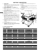
SECTION 1 - DESCRIPTION I. OVEN USES J. PS536GS ovens can be used to bake and/or cook a wide variety of food products, such as pizza, pizza-type products, cookies, sandwiches and others. Not Shown: ENGLISH II. OVEN COMPONENTS - see Figure 1-1. A. Window: Allows the user to see and access food products inside the baking chamber. B. Conveyor End Stop : Prevents food products from falling off the end of the moving conveyor. C.
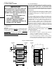
SECTION 1 - DESCRIPTION Main Blower Voltage Control Circuit Voltage 208/240V 120V conv. speed control & drive motor; all others as per line (208/240V) Phase Freq. Current Draw Poles Wires 1 Ph 50/60 Hz 6A * 2 Pole 3 Wire (2 hot, 1 gnd) * The current draw shown above is an average value for normal operation. The initial amperage draw on oven startup may exceed the listed value.
SECTION 2 - INSTALLATION WARNING - For gas ovens, after any conversions, readjustments, or service work on the oven: ENGLISH • • • • Perform a gas leak test. Test for correct air supply. Test for proper combustion and gas supply. Check that the ventilation system is in operation. WARNING Keep the appliance area free and clear of combustibles. WARNING The oven must be installed on an even (level) non-flammable flooring and any adjacent walls must be non-flammable.
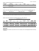
SECTION 2 - INSTALLATION Figure 2-1 - Installation Kit 2 3 4a, 4b, 4c, 4d 8 12 16 14 13 15 6 11 5 10 7 9 I. INSTALLATION KIT - see Figure 2-1 Item 1 Qty. Single Oven 1 Qty. Double Oven 1 Qty. Triple Oven 1 Part No. 48605 Inc. with domestic ovens? Yes Inc.
SECTION 2 - INSTALLATION B. II. VENTILATION SYSTEM NOTE THAT THE HOOD DIMENSIONS SHOWN IN FIGURE 22 ARE RECOMMENDATIONS ONLY. LOCAL, NATIONAL AND INTERNATIONAL CODES MUST BE FOLLOWED WHEN INSTALLING THE VENTILATION SYSTEM. ANY APPLICABLE CODES SUPERSEDE THE RECOMMENDATIONS SHOWN IN THIS MANUAL. IMPORTANT ENGLISH Where national or local codes require the installation of fire suppression equipment or other supplementary equipment, DO NOT mount the equipment directly to the oven.
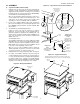
SECTION 2 - INSTALLATION III. ASSEMBLY Figure 2-3 - Leg extension and casters installation Top Panel and Base Pad Assembly 1. Install the four leg extensions onto the base pad using the 3/8"-16x1" screws, 3/8" flat washers, and 3/8" lockwashers supplied in the Base Pad Kit. See Figure 2-3. Check that the finished sides of each leg extension face OUTWARDS.
SECTION 2 - INSTALLATION B. Stacking 1. For single ovens, skip ahead to Part C, Restraint Cable Installation. Stack an oven cavity on top of the lower oven. Check the following: ENGLISH • All four sides of the lower lip (on the bottom edge of the oven cavity) overlap the top of the lower oven. IMPORTANT Middleby Marshall STRONGLY RECOMMENDS that PS536GS oven cavities be stacked using the following: • The oven is level. • The oven is firmly seated. • • See Figure 2-6.
SECTION 2 - INSTALLATION Conveyor Installation 1. Unfold the conveyor as shown in Figure 2-9. Then, begin to slide the conveyor into the end of the oven. The conveyor can only be installed from the end of the oven with the drive motor. 2. Continue moving the conveyor into the oven until the frame protrudes equally from each end of the oven. Check that the crumb tray supports located on the underside of the conveyor frame rest firmly against the lower end plugs, as shown in Figure 2-10. 3.
SECTION 2 - INSTALLATION 5. ENGLISH If it is necessary to add or remove conveyor links to achieve the correct tension, OR if it is necessary to reverse the conveyor belt for correct orientation, the belt will need to be removed from the conveyor frame. If this is necessary, perform the following procedure: E. Final Assembly 6. Install the drive chain between the conveyor drive sprocket and the motor sprocket. To install the chain, it will be necessary to lift the drive end of the conveyor slightly.
SECTION 2 - INSTALLATION WARNING Authorized supplier personnel normally accomplish the connections for the ventilation system, electric supply, and gas supply, as arranged by the customer. Following these connections, the factory-authorized installer can perform the initial startup of the oven. The oven requires a ground connection to the oven ground screw located in the electrical junction box. (The box is shown in Figure 2-14.
SECTION 2 - INSTALLATION V. GAS SUPPLY Appliances, ANSI Z21.69 (in U.S.A.), as well as a quick-disconnect device that complies with the Standard for Quick-Disconnect Devices for Use With Gas Fuel, ANSI Z21.41 (in U.S.A.). CAUTION DURING PRESSURE TESTING NOTE THE FOLLOWING: C. ENGLISH 1. The oven and its individual shutoff valve must be disconnected from the gas supply piping system during any pressure testing of that system at test pressure in excess of 1/2 psi (3.45 kPa).
5. 6. Gas Burner 7. 8. Disconnect electrical connection of the Moduplus®. Check minimum pressure setting and readjust if necessary. (See Adjusting Minimum Pressure Setting for proper adjusting procedure.) Reconnect pressure feedback connection (if appcable). If minimum and maximum pressures are set, wire the Moduplus® in circuit. 9. Close pressure tap screw. F. Adjusting the Minimum Pressure Setting 1. Disconnect pressure feedback connection (if appcable). 2.
SECTION 2 - INSTALLATION NOTES ENGLISH 16
ENGLISH SECTION 3 - OPERATION E D B A C I. LOCATION AND DESCRIPTION OF CONTROLS A. "BLOWER" Switch: Turns the blowers and cooling fans on and off. The HEAT Switch has no effect unless the BLOWER Switch is in the “ON” position. B. "HEAT" Switch: Allows the burner to activate. Activation is determined by the settings on the Digital Temperature Controller. C. "CONVEYOR" Switch: Turns the conveyor drive motor on and off. D. Conveyor Speed Controller: Adjusts and displays the bake time.
SECTION 3 - OPERATION II. NORMAL OPERATION - STEP-BY-STEP A. DAILY STARTUP PROCEDURE 1. Check that the circuit breaker/fused disconnect is in the on position. Check that the window is closed. ENGLISH 2. 3. 4. 5. 7. Wait for the oven to heat to the setpoint temperature. Higher setpoint temperatures will require a longer wait. The oven can reach a temperature of 500°F (232°C) in approximately 5 minutes. 8.
SECTION 3 - OPERATION Display ENGLISH III. QUICK REFERENCE: DIGITAL TEMPERATURE CONTROLLER "HEAT ON" Light Shows the Set Point or the Actual Temperature in degrees Fahrenheit (F) or Celsius (C). Lights when the burner is in operation. "SP LOCK" Light Lights when the set point is locked out from changes. This setting can only be changed by service personnel. "SET PT" (setpoint) Light Lights when the set point is shown in the display.
SECTION 4 - MAINTENANCE WARNING Before ANY cleaning or servicing of the oven, perform the following procedure: ENGLISH 1. 2. 3. 4. Switch off the oven and allow it to cool. Do NOT service the oven while it is warm. Turn the full-flow gas safety valve to the off position. Turn off the electric supply circuit breaker(s) and disconnect the electric supply to the oven. If it is necessary to move a gas oven for cleaning or servicing, disconnect the gas supply before moving the oven.
SECTION 4 - MAINTENANCE Figure 4-2 - Removing Air Fingers and Plates A. Check that the oven is cool and the power is disconnected, as described in the warning at the beginning of this Section. B. Refer to Part D, Conveyor Installation, in the Installation section of this Manual. Then, remove the following components from the oven: • Conveyor end stop • Crumb trays • Chain cover • Drive chain • End plugs • Conveyor assembly C.
SECTION 4 - MAINTENANCE ENGLISH 2. Remove the master links from each conveyor belt. Then, roll the belts up along the length of the conveyor to remove them from the frame. 3. Remove the two conveyor adjustment screws from the idler end of the conveyor frame, as shown in Figure 44. 4. Remove the idler shaft assembly from the conveyor. 5. Pull apart the two sections of the idler shaft. 6. Clean the shafts thoroughly using a rag.
Blower Belt 1. Remove the six screws shown in Figure 4-7. Then, remove the rear panel from the oven. 2. Check the blower belt for the proper 1/4" (6mm) deflection at the center, and for cracking or excessive wear. See Figure 4-7. Overtightening the belt will cause premature bearing failure and possible vibrations. A loose belt may also cause vibrations. 3. If necessary, adjust the tension of the belt by loosening the four motor mounting bolts.
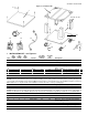
SECTION 5 - PARTS LIST SECTION 5 - PARTS LIST 1 4 2 5 3 7 6 8 13 11 9 10 12 15 14 16 I. KEY SPARE PARTS KIT ITEM QTY. P/N DESCRIPTION 1 1 47321 DIGITAL TEMPERATURE CONTROLLER 2 1 51067 CONVEYOR DRIVE MOTOR W/PICKUP ASSY.
SECTION 6 - ELECTRICAL WIRING DIAGRAMS SECTION 6 - ELECTRICAL WIRING DIAGRAMS 60968 Rev. D Fig. 6-1 - Wiring diagram, PS536GS Gas Oven 208/240V, 50/60 Hz, 1 Ph IMPORTANT An electrical wiring diagram for the oven is also located inside the machinery compartment.
NOTES
NOTES
WARNING Improper installation, adjustment, alteration, service or maintenance can cause property damage, injury or death. Read the installation, operating and maintenance instructions thoroughly before installing or servicing this equipment. NOTICE During the warranty period, ALL parts replacement and servicing should be performed by your Middleby Marshall Authorized Service Agent. Service that is performed by parties other than your Middleby Marshall Authorized Service Agent may void your warranty.