
Microwave Oven User Manual


11
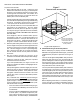
SECTION 2 - AIR FLOW AND HEAT TRANSFER
of making a test to read the bake.
1. Remove all upper air fingers from the oven.
NOTE: As the air fingers are removed, use a felt pen to
mark all parts of the fingers. This includes the mani-
fold, inner plate and outer plate. If a blank or choke
plate is used, mark that plate also. Fingers are marked
in the order shown below, as viewed from the front of
the oven. If there are upper and lower oven cavities,
you should mark the fingers for the upper oven with a
U and those for the lower oven with a L.
VERY IMPORTANT: When the ovens were shipped
from the factory, all of the shutters were pre-ad-
justed for their location within the oven. AII parts
of the fingers must be marked as explained above
and reassembled into their original position.
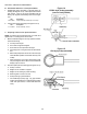
2. Check the size of the openings at the front of the shut-
ter plates by inserting a drill into the opening. The
factory setting is a #46 drill (0.081/2.06mm).
3. Drill out the four 1/8 pop rivets that are located toward
the front of the fingers. See Figure 8.
NOTE: DO NOT drill out the rivet at the back of the air
finger. This is the pivot for the shutter.
4. If the product is lighter at the front of the oven, increase
the opening by 1/16/1.59mm. If the product is darker
at the front of the oven, decrease the opening by 1/16/
1.59mm.
The best way to check the size of the openings is to
use numbered drills as a gauge. An orifice drill set is
ideal for making this adjustment. For example, to in-
crease the opening by 1/16, you would use a #30 drill
(0.1285/3.26mm), which is approximately 1/16 larger
than the original setting measured with the #46 drill
(0.081/2.06mm).
Be sure that the measurement is taken at the largest
point of the opening. See Figure 8.
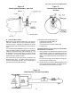
5. While holding the new adjustment, clamp the two shut-
ter plates together (two pairs of vice grip pliers are ideal)
and drill holes for new pop rivets.
NOTE: Most of the old rivet holes can be reused if the
old hole is simply elongated. However, if the hole is not
properly elongated, the new rivets may pull the plates
out of adjustment when they are installed.
IMPORTANT: Aluminum 1/8 pop rivets are ideal
for use here. They are much easier to drill out
than stainless steel rivets.
6. Repeat these steps to adjust all upper air fingers. Then,
reinstall the fingers into the oven.
7. Perform another test bake.
lMPORTANT: This test bake must be an exact dupli-
cate of the first test bake. If you change any of the
conditions you will change the results.
If the test indicates an even bake, your adjustment
is complete.
If the test indicates that the bake is still uneven,
you will need to repeat the adjustment procedure
until an even bake is obtained. By keeping the
tests identical, you should be able to determine
how much more the shutter plates should be opened
or closed to achieve a balanced bake without re-
moving the fingers for a third time.
VERY IMPORTANT: After attaining a proper adjust-
ment of the fingers, each air finger should be marked
with a metal stamp showing its position inside the oven.
This will eliminate future problems of operators mixing
the adjusted fingers when cleaning the oven.
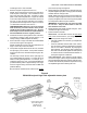
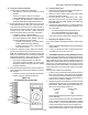
Figure 8
PS300/350-style air finger with adjustable shutter plate
Higher pressure at the
front of the fingers is
regulated by the
shutter openings
Pivot
DO NOT
drill out
Drill out
rivets
Vise grip
pliers
Insert drill bit
to check size
of opening