
Microwave Oven User Manual


32
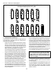
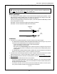
B. Description
The temperature controller consists of two main compo-
nents: a sleeve or case (metal or plastic) with terminal con-
nections on the back, and a plug-in chassis that includes
the faceplate and circuitry. The sleeve is mounted to the
panel or door of the oven, and the chassis is inserted into
the front of the sleeve.
VERY IMPORTANT: When replacing a controller, you
should ALWAYS replace the sleeve as well. Some control-
ler models have sleeves of a similar size, but with DIFFER-
ENT CONNECTIONS. Using an incorrect sleeve can dam-
age the controller and cause the oven to function incor-
rectly. Exception: The sleeve used on Controllers 36056
and 46837 is identical except for the information label.
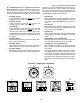
C. High Limit/Cooldown Functions
Except where noted in Section A (Part Number Reference),
the temperaturecontroller incorporates circuitry for the high
limit and cooldown functions.
1. The High Limit function (terminals 11 and 12) will shut
off the burner/heating elements if the oven temperature
sensed by the thermocouple(s) exceeds 650°F/343°C.
This function is used on most PS200-series and PS360-
series gas ovens. All other oven models use a sepa-
rate high limit control module.
If the high limit temperature is reached, an indicator on
the controller will illuminate. The current controller
(P/N 46837) has a lamp marked OVERTEMP to show
this condition. Older controllers will have different indi-
cators; you should refer to the operating instructions
for the controller in question for assistance.
2. The Cooldown function allows the blowers to continue
in operation after the operator switches off all operating
switches on the control panel. The blowers will remain
in operation until the cooldown switch opens (usually
180°F/82°C).
D. Troubleshooting
1. Troubleshooting the Temperature Controller and
Thermocouple(s) using the Altek Thermocouple Source
(Middleby P/N 27170-0192)
Turn the heat switch OFF.
Disconnect the thermocouple leads from Terminals
7 and 8 on the temperature controller. Tape the
ends to prevent shorting.
Connect the white lead of the Thermocouple Source
to Terminal 8 (+). Connect the red lead of the Ther-
mocouple Source to Terminal 7 (-).
Set the Thermocouple Source as close as pos-
sible to the customers set point. Then, turn the
BLOWER switch to the ON position.
The temperature controller should read close to the
customers set point. Failure indicates a problem with
the temperature controller. If the temperature control-
ler is functioning properly, check the thermocouples.
Refer to Section IV, Thermocouples.
2. Troubleshooting the High Limit Switch
On ovens that use the high limit function of the tem-
perature controller (most PS200-series and PS360-se-
ries ovens), an intermittent high limit switch will cause
intermittent operation of the burner. If you suspect that
this is a problem, a good check is to place a 1A fuse in
parallel around the switch contacts (terminals 11 and
12).
If the switch is functioning properly, the fuse will never
carry a load. The only time the switch would open
would be under a no-load condition.
If the switch is trying to open intermittently, however,
the full current load of the blowers will be carried by the
fuse. Regardless of the oven model, this load is far
greater than 1A, and the fuse will blow.
Terminal for Terminal for
28071-0012 and Terminal for 36056 and Description
28071-0018 34983 46837
1 TC+ 8 + TC
2TC-7 - TC
5 COM 5 Input to Temperature Control Relay
6 NO 4 Output to High Flame Solenoid or Heater Contactors
L2 L2 L2 Neutral
L1 L1 L1 Power
GG Ground
13 -- 9 Input to Cooldown Relay
14 -- 10 Output from Cooldown Relay
15 -- 11 Input to High Limit Relay
16 -- 12 Output from High Limit Relay
-- -- 15 PID or Variable Pulse Output
-- -- 16 PID or Variable Pulse Output
SECTION 3 - SERVICING COMPONENTS
E. Appendices
Appendix - Temperature controller terminal cross-reference, 4/02