
Microwave Oven User Manual


95
SECTION 3 - SERVICING COMPONENTS
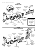
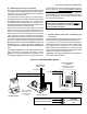
E. Burner Blower Motor
The burner blower motor is located on the side or top of the
burner housing. Some blowers use a flexible tube to con-
nect the blower to the burner, depending on the available
space inside the machinery compartment. The burner
blower motor drives a blower wheel located in a housing
attached to the end of the motor that is the primary air
supply for combustion. The motor requires no lubrication.
Depending on the oven model, the burner motor operates
on either 120V or 208/240V (line voltage). 120V motors
have an internal centrifugal switch that controls the 24V
power supply to the gas valve (see Burner Blower Motor
Centrifugal Safety Switch on Page 80). 208/240V motors
use a separate air pressure safety switch to sense blower
operation (see Air Pressure Safety Switch on Page 81).
This safety feature prevents burner operation in case of motor
failure.
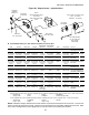
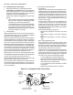
F. Air Shutter
The air shutter is a round metal plate located on the open
end of the burner blower wheel. Adjusting the position of
the shutter will increase or decrease the amount of air that
is permitted into the plenum for combustion. Rotate the
plate in a counterclockwise direction to increase the air
supply, or in a clockwise direction to reduce the air supply.
You can insert a drill bit into the shutter gap to check the
size of the opening. Refer to Figure 69 for the recommended
opening sizes.
Early Midco burners use an adjustment screw on the front
wall of the plenum to adjust the airflow. If it is not possible
to adjust the air supply properly using the screw, a retrofit
kit is available (P/N 36829) to install the external air shutter
shown in Figure 69.
Figure 69
Air shutter adjustment
Counter-
clockwise -
more air
Clockwise -
less air
Wayne burner
Standard openings:
1/4/6.4mm for natural gas ovens
3/8/9.5mm for propane ovens
Midco burner
Standard opening 5/16/7.9mm (all gases)
Loosen
screw to
adjust
shutter
Loosen hex
nut to adjust
shutter
Clockwise -
less air
Counterclockwise -
more air
In these cases, the pilot may ignite, but the main burner
gas valve will not be energized. It is also possible for
drafts or unusual air currents to deflect the pilot flame
away from the flame sensor. Deflection of the pilot
flame may also be caused by main burner ignition con-
cussion or roll-out of the main burner flame.
An additional point to be considered is the condition of
the pilot flame. If the pilot flame is hard and blowing,
the grounding area of the pilot is reduced to a point
where the necessary current is not being maintained,
and a shutdown of the system will result.
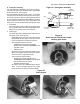
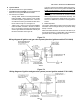
The positioning of the flame sensor is also critical in
the pilot application. Positioning of the flame sensor
should be such that it will be in contact with the sec-
ond, or combustion area of the pilot flame. Passing
the flame sensor through the inner cone of the pilot
flame is not a recommended procedure. For this rea-
son, a short flame sensor may provide a superior sig-
nal over a longer one. The final determination of the
sensor location (length) is best determined by the use
of a multimeter set to read microamps (mA).
Temperature
Ignition controls should not be exposed to tempera-
tures exceeding 140°F (60°C) or less than -40°F (-40°C).
Pilot Application
The pilot and flame sensor application is the most criti-
cal aspect of the llD application.
The pilot flame must make contact with the pilot tip
and surround the flame sensor probe. A multimeter or
ampmeter set to read microamps (mA) is necessary to
verify that the proper amount of current is being main-
tained through the pilot flame. The minimum value
required is 2.0 mA. Rectification-based ignition sys-
tems respond in less than 0.8 of a second to a loss of
flame. If the minimum signal is not being maintained
at all times, OR if the pilot flame is briefly directed
away from the flame sensor or pilot tip, the main gas
valve may cycle rapidly (chattering) or the burner may
be prevented from activating.
Other conditions that can cause the failure of the main
burner to activate, OR chattering of the burner, are:
1. Pilot flame is too small.
2. Gas pressure is too low for proper pilot flame im-
pingement on the flame sensor.