
Microwave Oven User Manual


96
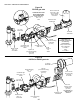
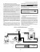
G. Burner Transformer
120V burner blower motors feature a transformer located in
the electrical junction box on the burner. In PS570S ovens,
AND all ovens with 208/240V burner blower motors, the
transformer is located inside the machinery compartment.
The transformer supplies 24V to the burner motor relay (if
present) and also to the 24V gas valve through the motors
centrifugal switch (or air pressure safety switch).
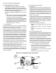
H. Burner Motor Relay
120V burner blower motors feature a 24V time delay relay
located in the electrical junction box on the burner. In
PS570S ovens, the relay is located on the back wall of the
machinery compartment.
Approximately 25 seconds after power is applied to the coil
of the relay, the contacts will close and complete a circuit
to the burner blower, allowing the motor to operate. This
15-30 second delay is a prepurge for a cold start. When
the coil of the relay is warm, the delay is bypassed.
Ovens with 208/240V burner blower motors are not equipped
with the burner motor relay, and do not have a prepurge for
a cold start.
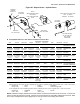
I. High Flame Solenoid Valve (if so equipped)
Ovens that use an on-off gas regulation system are equipped
with a high flame solenoid valve. The valve is located be-
tween the combination gas control valve and the burner.
The valve operates on 110-120V.
The valve opens when the ovens temperature falls 2 de-
grees Fahrenheit below the set point, and closes when the
temperature rises to 2 degrees above the set point. Be-
cause of residual heat within the oven, however, the tem-
perature swing after preheating is about 5 degrees Fahren-
heit above and below the set point.
The solenoid valve can only be positioned fully open (100%
gas flow) or fully closed (0% gas flow). While the valve is
closed, gas is still supplied to the burner through the by-
pass line that goes around the solenoid valve. This allows
the burner to operate in low flame mode while awaiting re-
activation.
When the oven has been fully preheated and has main-
tained the set point for about an hour with a moderate prod-
uct load, the low flame to high flame ratio should be ap-
proximately 1 to 1. That is, the oven will be calling for heat
approximately half the time. To check this ratio, refer to
the HEAT indicator on the temperature controller, which will
only be active when the burner is on high flame.
EXCEPTION: Older PS310/314/360 ovens have a tempera-
ture-sensing thermocouple mounted at the front of the oven,
inside the machinery compartment. On these ovens, the
low flame to high flame ratio should be approximately 2 or 3
to 1 (oven calls for heat 1/3 or 1/4 of the time).
SECTION 3 - SERVICING COMPONENTS
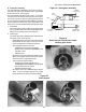
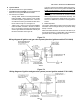
Figure 70
Low Flame (Bypass) Orifice
Bypass line configuration varies depending on the oven model. Refer to the drawings on pages 88-90.
Solenoid
valve
Bypass
line
Low flame
(bypass)
orifice
IMPORTANT: For proper functioning of the sole-
noid valve, the temperature controller MUST be
set to the on-off operating mode. Refer to Tem-
perature Controller on Page 31.
J. Bypass (Low Flame) Orifice (ovens with a high
flame solenoid valve only)
All ovens that use an on-off gas regulation system are
equipped with an orifice in the low flame bypass line. See
Figure 70.
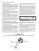
When the oven is not calling for heat, the solenoid valve is
closed, but gas is still supplied to the burner through the
bypass line. This allows the burner to operate in low flame
mode while awaiting re-activation.
The low flame orifice regulates the gas flow through the
bypass line. If the orifice size is too large, the low flame
will be too high. In some cases, this will prevent the oven
from being able to maintain the set point.
Refer to the chart on Page 91 to determine the proper size
for the bypass orifice.