technical service manual This Technical Service Manual includes information for the following oven models: PS200/220/224 Series PS310/360 Series PS555/570 Series P/N 47829 Rev. C V1 4/02 Middleby is proud to support the Commercial Food Equipment Service Association (CFESA). We recognize and applaud CFESAs ongoing efforts to improve the quality of technical service in the industry. © 2002 Middleby Marshall, Inc. is a registered trademark of Middleby Marshall, Inc. All rights reserved.
WARNING Improper installation, adjustment, alteration, service or maintenance can cause property damage, injury or death. Read the installation, operating and maintenance instructions thoroughly before installing or servicing this equipment. WARNING DISCONNECT THE OVEN FROM ITS ELECTRICAL POWER SUPPLY BEFORE SERVICING. NOTICE During the warranty period, ALL parts replacement and servicing should be performed by your Middleby Marshall Authorized Service Agent.
TABLE OF CONTENTS (continued) III. High Limit Control Module ........................................................... 45 A. Part Number Reference - High Limit Control Modules ...... 45 B. Location .............................................................................. 45 C. Troubleshooting .................................................................. 45 D. Appendices .........................................................................
SECTION 1 - SEQUENCE OF OPERATION SECTION 1 SEQUENCE OF OPERATION I. GAS OVEN SEQUENCE OF OPERATION D. Blower Switch A. Electrical Supply Closing the blower switch energizes: Gas heated ovens operate on 208/240V, single phase. Standard incoming power configurations are: 1. The cooling (axial) fan(s). 1. 4-wire system (PS200 series, PS310/360 series, PS570, PS570S) - 2 single phase 208/240V supply (hot) lines, 1 neutral and 1 ground. Closing this contactor starts the blower motor(s).
SECTION 1 - SEQUENCE OF OPERATION e. For ovens with an On-Off gas regulation system (with solenoid valve): Temperature Controller terminals 4 & 5 (power for the primary relay contacts for the high flame solenoid valve). F. High Limit NOTE: Most PS200-Series and PS360-series gas ovens use the high limit feature of the Temperature Controller. All other oven models use a separate High Limit Control Module.
SECTION 1 - SEQUENCE OF OPERATION ll. E. Heat Switch Closing the heat switch completes a circuit: ELECTRIC OVEN SEQUENCE OF OPERATION A. Electrical Supply 1. Through the heat switch. 2. Through the blower motor centrifugal switch. Most electrically heated ovens operate on a 208/230/ 380/440V, 3 phase, 4 wire system. The fourth wire is for a 120 V neutral ground. This 120 V neutral ground eliminates the need for a control transformer. Where a neutral is not available, a 240/110V transformer is supplied.
SECTION 2 - AIR FLOW AND HEAT TRANSFER SECTION 2 AIR FLOW AND HEAT TRANSFER I. In Middleby Marshall conveyor ovens, the heat transfer from conduction is greatly dependent on the customers product and cooking surface (pans, etc.). Likewise, the heat transfer from radiation is effectively constant, because the color of the oven interior cannot be changed. For these reasons, the best way to optimize heat transfer is by regulating the convection air.
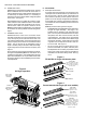
SECTION 2 - AIR FLOW AND HEAT TRANSFER III. AIR FINGERS B. PS360-series ovens A. Description and Function PS360-series ovens feature two blower motors. A blower wheel is fastened onto the end of the motor shaft. In order to adjust the amount and speed of heated air that is directed by the blower wheels, it is necessary to change the size of the wheels and/or change the speed of the motor. See Figure 1.
SECTION 2 - AIR FLOW AND HEAT TRANSFER B. Configuration and Alignment 2. Check that the bake time and temperature settings of the oven match the customers specifications. Most customers have an acceptable range for bake time and temperature to allow for local variations in altitude, humidity, etc. To ensure proper baking of the product, the air flow MUST be properly aligned as it exits the air fingers.
SECTION 2 - AIR FLOW AND HEAT TRANSFER Figure 7 Front-to-back uneven bake To perform the test bake: 1. Select identical pans for the test. Choose the pans based on the width of the conveyor; you should space the pans in line completely across the conveyor without having them touch each other. For instance, for a 32 /813mm-wide conveyor, you could use three 10/ 254mm pans or two 15/381mm pans. You will need enough pans to have three complete rows.
SECTION 2 - AIR FLOW AND HEAT TRANSFER of making a test to read the bake. point of the opening. See Figure 8. 1. Remove all upper air fingers from the oven. 5. While holding the new adjustment, clamp the two shutter plates together (two pairs of vice grip pliers are ideal) and drill holes for new pop rivets. NOTE: As the air fingers are removed, use a felt pen to mark all parts of the fingers. This includes the manifold, inner plate and outer plate.
SECTION 2 - AIR FLOW AND HEAT TRANSFER IV. OVEN CAPACITY B. Belt Time Oven capacity is generally not a service issue. However, when reporting a service problem, customers may use terms relating to capacity, such as bake time, belt time, time of delivery, etc. This information is provided as a reference for understanding these terms. Belt Time is a measurement used by several customers. It is a trailing edge to trailing edge measurement.
SECTION 3 - SERVICING COMPONENTS SECTION 3 SERVICING COMPONENTS I. CONVEYOR SPEED CONTROLLER AND DRIVE MOTOR A. Part Number Reference - Speed Controllers 1. Original-style speed controller with interchangeable microcomputer and thumbwheel. This unit is no longer available and part numbers are provided for reference only. Servicing this unit is beyond the scope of this manual. If this controller is in need of service, we recommend simply installing a current unit (see below).
SECTION 3 - SERVICING COMPONENTS Figure 14 PS350-style pickup assembly (used on early PS360) B. Part Number Reference - Pickup Assemblies 1. PS350-style pickup assembly or old-style pickup assembly (see Figures 14-15). These parts use the same part number. They are no longer available from the factory, but may still be stocked by some service agencies. P/N 28074-0005 Description Pickup assembly, PS350-style or old-style 2.
SECTION 3 - SERVICING COMPONENTS Figure 16 Current pickup assembly - side view Figure 17 Current pickup assembly end view Components needed for the field tester: Full-wave AC-DC bridge, 400V, 4A Light dimmer switch, 5A In-line 5A AC fuse enclosed in plastic case 2 alligator clips D. Controller/Motor Failure When the conveyor speed controller fails, it is very possible that a shorted conveyor motor caused the problem.
SECTION 3 - SERVICING COMPONENTS E. Basic Troubleshooting Flowcharts 1. IF THE GEAR MOTOR RUNS AT FULL SPEED: NOTE: Middleby no longer stocks parts for the original speed controller with interchangeable microcomputer. If it is necessary to replace this version of the controller or the microcomputer, and the service agent does not have the parts in stock, it will be necessary to replace the entire speed controller with a current model.
SECTION 3 - SERVICING COMPONENTS 2. IF THE GEAR MOTOR WILL NOT RUN AT ALL: NOTE: Middleby no longer stocks parts for the original speed controller with interchangeable microcomputer. If it is necessary to replace this version of the controller or the microcomputer, and the service agent does not have the parts in stock, it will be necessary to replace the entire speed controller with a current model.
SECTION 3 - SERVICING COMPONENTS F. Initial Troubleshooting 3. With the AC power on, check the DC voltage to the conveyor motor. Match the measured voltage with those shown on the chart below. If the voltage reading is more than ±5VDC of that shown on the chart, complete the Motor Test on the next page. NOTE: When changing the conveyor speed on a controller with a thumbwheel, it is advisable to turn the conveyor switch OFF before adjusting the thumbwheel.
SECTION 3 - SERVICING COMPONENTS G. Conveyor Control Pickup Test H. Conveyor Motor Test 1. Visually check the pickup for the following: The magnet is clean and the bearing is in good condition. There are no chips or cracks on the magnet. If using a PS350-style pickup (see Figure 14), there is a 1/64 to 1/32 (0-4-0.8mm, or a business card thickness) gap between magnet and hall device. 1. Disconnect the gear motor wires from the Speed Controller terminals (-ARM and +ARM). 2.
SECTION 3 - SERVICING COMPONENTS Figure 20 Wiring for PS360 Shielded Pickup Cable - early terminal block design Figure 21 Wiring for PS360 Shielded Pickup Cable - late terminal block design K.
SECTION 3 - SERVICING COMPONENTS Appendix - Service Bulletin MM-133B - Installation Instructions for Conveyor Speed Controller Kit with Thumbwheel, P/N 42810-0133, 4/95 21
SECTION 3 - SERVICING COMPONENTS Appendix - Service Bulletin MM-133B - Installation Instructions for Conveyor Speed Controller Kit with Thumbwheel, P/N 42810-0133, 4/95 22
SECTION 3 - SERVICING COMPONENTS Appendix - Instructions for Service Kit 42810-0133Conveyor Speed Controller Kit with Thumbwheel, 4/95 23
SECTION 3 - SERVICING COMPONENTS Appendix - Instructions for Service Kit 42810-0133Conveyor Speed Controller Kit with Thumbwheel, 4/95 24
SECTION 3 - SERVICING COMPONENTS Appendix - Instructions for Service Kit 42810-0133Conveyor Speed Controller Kit with Thumbwheel, 4/95 25
SECTION 3 - SERVICING COMPONENTS Appendix - Instructions for Service Kit 42810-0133Conveyor Speed Controller Kit with Thumbwheel, 4/95 26
SECTION 3 - SERVICING COMPONENTS Appendix - Service Bulletin MM-177 - Introduction and Compatibility of Conveyor Speed Controller with Digital Display, P/N 37337, 8/00 Bulletin No. MM-177 Date: 8/18/00 Middleby Cooking Systems Group 1400 Toastmaster Drive Elgin, IL 60120-9272 U. S. A.
SECTION 3 - SERVICING COMPONENTS Appendix - Instructions for Service Kit 44756 - Conveyor Speed Controller Kit for PS200R68-series Ovens, 2/02 Middleby Cooking Systems Group 1400 Toastmaster Drive Elgin, IL 60120 USA (847) 741-3300 FAX (847) 741-4406 Instructions for Service Kit 44756 Conveyor Speed Controller Kit for PS200R68-series ovens KIT COMPONENTS: Qty.
SECTION 3 - SERVICING COMPONENTS Appendix - Service Bulletin MM-189 - New Conveyor Gear Motors, Brushes, and Pickup Clamps, 8/01 Bulletin No. MM-189 Date: 8/24/01 Middleby Cooking Systems Group 1400 Toastmaster Drive Elgin, IL 60120-9272 U. S. A.
SECTION 3 - SERVICING COMPONENTS Appendix - DIP switch settings for Conveyor Speed Controller with Digital Display (P/N 37337), 4/02 For this operating mode, the temperature controller is set to the On-Off Mode as described in the Kit instructions. II. TEMPERATURE CONTROLLER The Temperature Controller is used to set and control the oven temperature.
Middleby Marshall ovens have used several different models of temperature controllers. The current Digital Temperature Controller (P/N 46837, included in Service Kit 47321) is the only model currently available. All other controllers SECTION 3 - SERVICING COMPONENTS shown are no longer available and part numbers are provided for reference only. Servicing these units is beyond the scope of this manual.
SECTION 3 - SERVICING COMPONENTS D. Troubleshooting 1. Troubleshooting the Temperature Controller and Thermocouple(s) using the Altek Thermocouple Source (Middleby P/N 27170-0192) Turn the heat switch OFF. Disconnect the thermocouple leads from Terminals 7 and 8 on the temperature controller. Tape the ends to prevent shorting. Connect the white lead of the Thermocouple Source to Terminal 8 (+). Connect the red lead of the Thermocouple Source to Terminal 7 (-).
SECTION 3 - SERVICING COMPONENTS Appendix - Instructions for Service Kit 47321 - Digital Temperature Controller Kit, 2/02 Middleby Cooking Systems Group 1400 Toastmaster Drive Elgin, IL 60120 USA (847) 741-3300 FAX (847) 741-4406 Instructions for Service Kit 47321 Digital Temperature Controller Installation, Programming and Troubleshooting Instructions KIT COMPONENTS Qty.
SECTION 3 - SERVICING COMPONENTS Appendix - Instructions for Service Kit 47321 - Digital Temperature Controller Kit, 2/02 Controller Types This Kit includes one Digital Temperature Controller (P/N 46837) that can operate at 120-240V, and can be programmed to operate in on-off, PID, or variable pulse modes. The Controller is shown in Figure 1G, below. By following these instructions, the Controller can be installed into any Middleby Marshall oven equipped with the following Controllers.
SECTION 3 - SERVICING COMPONENTS Appendix - Instructions for Service Kit 47321 - Digital Temperature Controller Kit, 2/02 WARNING BEFORE PERFORMING ANY SERVICE WORK, THE ELECTRICAL POWER SUPPLY AND THE GAS SUPPLY MUST BE TURNED OFF. Before you Begin 1. This Temperature Controller requires a current-version thermocouple for proper operation. Check that the thermocouple(s) installed in the oven match the current three-lead, flanged versions BEFORE you begin to install the Temperature Controller.
SECTION 3 - SERVICING COMPONENTS Appendix - Instructions for Service Kit 47321 - Digital Temperature Controller Kit, 2/02 5. Check that the new controller is mounted into its sleeve. Then, slide the assembly into the opening in the panel from the outside. Check that the controller is upright, with the display on top and the keypad on the bottom. 6. Locate the rectangular holes on the top and bottom of the new controllers sleeve.
SECTION 3 - SERVICING COMPONENTS Appendix - Instructions for Service Kit 47321 - Digital Temperature Controller Kit, 2/02 Figure 4a Figure 4b Analog temperature controller (P/Ns 28071-0012 and 28071-0018) terminals Analog temperature controller (P/N 34983) terminals New temperature controller terminals New temperature controller terminals Not used on some gas and electric ovens Not used Not used. PS200VL ovens have a separate high limit module and do not include a cooldown feature.
SECTION 3 - SERVICING COMPONENTS Appendix - Instructions for Service Kit 47321 - Digital Temperature Controller Kit, 2/02 Jumper Setting Loosen the Phillips screw at the bottom center of the faceplate. Then, pull the controller out of its sleeve. Next, access the jumper shown in Figure 6. This jumper affects the signal that is output from Terminals 15 and 16. The jumper MUST be set to the correct position for proper operation of the controller.
SECTION 3 - SERVICING COMPONENTS Figure 7 Temperature Controller Service Instructions Appendix - Instructions for Service Kit 47321 - Digital Temperature Controller Kit, 2/02 Page 7 of 10 39
SECTION 3 - SERVICING COMPONENTS Appendix - Instructions for Service Kit 47321 - Digital Temperature Controller Kit, 2/02 Diagnostic Error Messages The controller runs background tests during normal operation. If any problems occur during the tests, an error message flashes in the display. A listing of these diagnostic error messages is shown below. Flashes on the display (alternating with the temperature) indicating that the internal diagnostic test has failed.
SECTION 3 - SERVICING COMPONENTS Appendix - Instructions for Service Kit 47321 - Digital Temperature Controller Kit, 2/02 Digital Temperature Controller P/N 46837 Operating Instructions "SP LOCK" Light Lights when the set point is locked out from changes. This setting can only be changed by service personnel. Display Shows the Set Point or the Actual Temperature in degrees Fahrenheit (F) or Celsius (C).
SECTION 3 - SERVICING COMPONENTS Appendix - Instructions for Service Kit 47321 - Digital Temperature Controller Kit, 2/02 Middleby Cooking Systems Group 1400 Toastmaster Drive Elgin, IL 60120 (847) 741-3300 FAX (847) 741-4406 Middleby Corporation Service Hotline 1-800-238-8444 42
SECTION 3 - SERVICING COMPONENTS Appendix - Service Bulletin MM-136 - Electrical Noise Filter Capacitor Assembly on Temperature Controllers, 9/93 43
SECTION 3 - SERVICING COMPONENTS Appendix - Service Bulletin MM-136 - Electrical Noise Filter Capacitor Assembly on Temperature Controllers, 9/93 44
SECTION 3 - SERVICING COMPONENTS III. HIGH LIMIT CONTROL MODULE C. Operation and Troubleshooting On most PS200-series and PS300-series gas ovens, the temperature controller monitors the high limit. All other oven models use a High Limit Control Module that is independent of the temperature controller. Refer to the wiring diagrams at the back of this manual for high limit wiring connections. The Watlow high limit control module generally uses a dedicated high limit thermocouple.
SECTION 3 - SERVICING COMPONENTS D. Appendices Appendix - Instructions for Service Kit 39733 High Limit Conversion Kit for PS300, 310, 350 & 360 Ovens, 5/99 Middleby Cooking Systems Group 1400 Toastmaster Drive Elgin, IL 60120 USA (847) 741-3300 FAX (847) 741-4406 Instructions for Service Kit 39733 High Limit Conversion Kit for PS300, 310, 350, & 360 Ovens KIT COMPONENTS - Check that the kit includes ALL of these parts BEFORE you begin! Qty.
SECTION 3 - SERVICING COMPONENTS Appendix - Instructions for Service Kit 39733 High Limit Conversion Kit for PS300, 310, 350 & 360 Ovens, 5/99 B. INSTALLATION WARNING BEFORE PERFORMING ANY SERVICE WORK, THE GAS SUPPLY (IF SO EQUIPPED) AND THE ELECTRICAL SUPPLY TO THE OVEN MUST BE TURNED OFF. 1. Open the machinery compartment and control compartment access panels. 2. Locate the high limit thermo bulb/capillary assembly. Its location is shown in Figure 2.
SECTION 3 - SERVICING COMPONENTS Appendix - Instructions for Service Kit 39733 High Limit Conversion Kit for PS300, 310, 350 & 360 Ovens, 5/99 Figure 2 High limit thermocouple location lower oven High limit thermocouple location upper oven Figure 3 Figure 4 NOT TO SCALE Figure 5 Figure 6 Thermocouple Base Sleeve Hole in sleeve is next to base of thermocouple Page 3 of 8 48
SECTION 3 - SERVICING COMPONENTS Appendix - Instructions for Service Kit 39733 High Limit Conversion Kit for PS300, 310, 350 & 360 Ovens, 5/99 C. WIRING For the various wiring connections listed below, cut the kit-supplied #18 AWG wires to length. Refer to Figures 7 and 8 (on pages 6 and 7) for diagrams of the wiring connections. Lighted Reset Switch Wiring and Installation 14. Using the kit-supplied 1/4 wire connectors, connect the following kit-supplied wires: - Red wires .................
SECTION 3 - SERVICING COMPONENTS Appendix - Instructions for Service Kit 39733 High Limit Conversion Kit for PS300, 310, 350 & 360 Ovens, 5/99 D. TESTING THE INSTALLATION 22. Remove the thermocouple wires from the TC + and TC - terminals on the high limit control. 23. Attach a Middleby Marshall Thermocouple Source (P/N 27170-0263) to the TC + and TC - terminals on the high limit control, in place of the thermocouple wires.
SECTION 3 - SERVICING COMPONENTS KEY Figure 7 - United Electric Model 55 replacement: ovens with a cooldown feature Appendix - Instructions for Service Kit 39733 High Limit Conversion Kit for PS300, 310, 350 & 360 Ovens, 5/99 Page 6 of 8 51
SECTION 3 - SERVICING COMPONENTS KEY Figure 8 - United Electric Model 54 replacement: ovens without a cooldown feature Appendix - Instructions for Service Kit 39733 High Limit Conversion Kit for PS300, 310, 350 & 360 Ovens, 5/99 Page 7 of 8 52
SECTION 3 - SERVICING COMPONENTS Appendix - Instructions for Service Kit 39733 High Limit Conversion Kit for PS300, 310, 350 & 360 Ovens, 5/99 A MIDDLEBY COMPANY Middleby Cooking Systems Group 1400 Toastmaster Drive Elgin, IL 60120 USA (847) 741-3300 FAX (847) 741-4406 Middleby Corporation Service Hotline 1-800-238-8444 www.middleby.
SECTION 3 - SERVICING COMPONENTS Figure 24 - Thermocouples IV. THERMOCOUPLES All temperature controller and high limit functions are based on input from thermocouples. When two wires composed of dissimilar metals are joined together and one of the ends is heated, a continuous current flow is generated. Middleby ovens use a Type J (iron constant) thermocouple. The iron wire increases the number of dissimilar metal junctions in the circuit. Middleby has used several types of thermocouples.
SECTION 3 - SERVICING COMPONENTS 2. Checking the thermocouple with a DC millivolt meter It is possible to check that a thermocouple is reading accurately by using a multimeter set to read DC millivolts. At 32°F/0°C the thermocouple should read 0 mVDC. This can be checked by inserting the ther- mocouple into an ice bath for several minutes. At 72°F/ 22°C the reading should be 1.134mVDC. You can use the chart below by checking the temperature at the thermocouples junction terminals.
SECTION 3 - SERVICING COMPONENTS D.
SECTION 3 - SERVICING COMPONENTS Appendix - Instructions for Service Kits 33984 and 33985 Oven Thermocouple Kit, 11/01 PS200 Series - before 2/96, serial numbers before ASH-0001 Figure 1 Thermocouple Installation - PS200 Series Thermocouples on these ovens are located inside the machinery compartment. They are secured in place by a set screw in the mounting tube, inside the plenum chamber. Thermocouple This Kit eliminates the set screw.
SECTION 3 - SERVICING COMPONENTS Appendix - Instructions for Service Kits 33984 and 33985 Oven Thermocouple Kit, 11/01 PS360 Series rear wall thermocouples before 2/96, serial numbers before ASH-0001 Figure 3 Thermocouple Installation - PS360 Series Thermocouples on these ovens are located on the rear wall of the baking chamber. They are secured in place by a clamp on the outside of the oven. Mounting tube (welded to plenum) Thermocouple This Kit eliminates the clamp.
SECTION 3 - SERVICING COMPONENTS Appendix - Instructions for Service Kits 33984 and 33985 Oven Thermocouple Kit, 11/01 PS360 Series front-mounted thermocouple inside the machinery compartment Figure 5 Thermocouple Installation - PS360 Series Machinery Compartment These thermocouples are mounted in a tube that extends diagonally up and into the plenum chamber. They are secured in place by a set screw located on the mounting tube, and by a bead of high-temperature silicone around the end of the shaft.
SECTION 3 - SERVICING COMPONENTS Appendix - Instructions for Service Kits 33984 and 33985 Oven Thermocouple Kit, 11/01 PS536 Figure 7 Thermocouple Installation - PS536 Thermocouples on these ovens are located inside the machinery compartment. They are secured in place by a sheet metal screw that traps the thermocouple flange against the wall of the compartment. See Figure 7. Sheet metal screw NOTE FOR HIGH LIMIT THERMOCOUPLES: PS536 ovens have two thermocouples, one mounted above the other.
SECTION 3 - SERVICING COMPONENTS Appendix - Instructions for Service Kits 33984 and 33985 Oven Thermocouple Kit, 11/01 PS555 Gas - thermocouples with screw terminal connections (no terminal blocks) 3. Disconnect the thermocouple leads. Refer to Figure 9. Thermocouples on these ovens are located on the rear wall. They are secured in place by two screws that are inserted through the holes in the thermocouple flange.
SECTION 3 - SERVICING COMPONENTS Appendix - Instructions for Service Kits 33984 and 33985 Oven Thermocouple Kit, 11/01 PS555 Electric and PS555E Note that all of the rear wall thermocouples are connected to the terminal block inside the left blower motor compartment. It is not necessary to access the right blower motor compartment. Temperature-sensing thermocouples on these ovens are located on the rear wall. High limit thermocouples are located inside the machinery compartment.
SECTION 3 - SERVICING COMPONENTS Appendix - Instructions for Service Kits 33984 and 33985 Oven Thermocouple Kit, 11/01 PS570 (X01-X05 name plate ID numbers) and PS570S (early) with side-mounted thermocouples inside or outside the blower motor compartments 7. Refer to Figure 11. Measure and scribe marks in the rear wall of the oven for drilling the thermocouple mounting holes.
SECTION 3 - SERVICING COMPONENTS Appendix - Instructions for Service Kits 33984 and 33985 Oven Thermocouple Kit, 11/01 Figure 11 Location of New Thermocouple Mounting Holes - PS570, PS570S High limit thermocouple position for ovens with LEFT-TO-RIGHT conveyors High limit thermocouple position for ovens with RIGHT-TO-LEFT conveyors Thermocouple positions for non-Pizza Hut/Tricon ovens Thermocouple positions for Pizza Hut/Tricon ovens Figure 12a Thermocouple Wiring - PS570 and PS570S (early) after therm
SECTION 3 - SERVICING COMPONENTS Appendix - Instructions for Service Kits 33984 and 33985 Oven Thermocouple Kit, 11/01 2. Remove the screws that hold the thermocouple to the wall. Slide the thermocouple out of its mounting hole. PS570S (late) - rear wall thermocouples with left-side AND right-side terminal block connections 3. Disconnect the thermocouple leads. Remove and discard the thermocouple.
SECTION 3 - SERVICING COMPONENTS Appendix - Instructions for Service Kits 33984 and 33985 Oven Thermocouple Kit, 11/01 Figure 14a Thermocouple Wiring - PS570S (Late) - Left to Right Conveyor NOTE: This configuration shows leads for three temperature-sensing thermocouples - two on the left side, and one on the right. Ovens with only two temperature-sensing thermocouples will have a single set of leads on the left terminal block, instead of the two sets that are shown.
SECTION 3 - SERVICING COMPONENTS Appendix - Instructions for Service Kits 33984 and 33985 Oven Thermocouple Kit, 11/01 PS555G and PS570G rear wall thermocouples with left-side terminal block connections 2. Remove the screws that hold the thermocouple to the wall. Slide the thermocouple out of its mounting hole. Thermocouples on these ovens are located on the rear wall. They are secured in place by two screws that are inserted through the holes in the thermocouple flange.
SECTION 3 - SERVICING COMPONENTS Figure 25 Early-style PS200 indirect drive assembly V. BLOWERS A. PS200-series ovens All PS200 ovens are equipped with one 1/3hp blower motor. The motor indirectly drives a pulley on the shaft of the blower fan with a fan belt. Two main designs exist for the PS200 indirect fan drive assembly: Early design, used through 6/90. This design used 1/2 (12.7mm) bore flange mount bearings and a 1/2 (12.7mm) diameter blower fan shaft. See Figure 25.
SECTION 3 - SERVICING COMPONENTS Figure 28 Bearing lubrication 2. Blower balancing and direction of rotation Proper blower rotation is extremely important. From the rear of the oven, the blower shaft pulley should turn in a clockwise direction. See Figures 25 and 26. Grease fittings (1 per bearing, 2 total) All blower fans are balanced at the factory. Any fan found to be out of balance should be replaced. Vibration from an out-of-balance fan can cause poor baking and premature bearing failure.
SECTION 3 - SERVICING COMPONENTS 5. Early-style PS200 bearing replacement and alignment NOTE: This procedure is for early-style indirect fan shaft assemblies only, as shown in Figure 25. Bearing replacement procedures for the current-style indirect fan shaft assembly (Figure 26) are provided on Page 72.
SECTION 3 - SERVICING COMPONENTS Figure 32 Bearing replacement and alignment - early-style PS200 fan shaft assembly Item Qty. Part Number Description 1 1 Not available Back Wall Assembly Item Qty.
SECTION 3 - SERVICING COMPONENTS 6. Current-style PS200 bearing replacement and alignment 7. Insert fan shaft alignment tool (Item 13) as shown into back wall. NOTE: This procedure is for current-style indirect fan shaft assemblies only, as shown in Figure 26. Bearing replacement procedures for the early-style indirect fan shaft assembly (Figure 25) are provided on Page 70.
SECTION 3 - SERVICING COMPONENTS Figure 34 Bearing replacement and alignment - current-style PS200 fan shaft assembly Item Qty. Part Number Description Item Qty. Part Number Description 1 1 37900-0068 Back Wall Assembly 11 1 27399-0003 Blower Fan, 16 Dia.
SECTION 3 - SERVICING COMPONENTS Figure 35 Blower motor fuses - single-phase motors B. PS360-series ovens All PS360-series ovens are equipped with two blower motors. All gas ovens have motors rated at 230V, single-phase. All electric ovens built before 8/02 have three-phase motors. All electric ovens built 8/02 or later that operate on a supply voltage of 208-240V have single-phase motors. All electric ovens built 8/02 or later that operate on supply voltages above 240V have three-phase motors.
SECTION 3 - SERVICING COMPONENTS 3. Direction of blower rotation 4. Removing the blower wheels Proper blower rotation is extremely important. Blower rotation is determined by viewing the motor and wheel from the REAR of the motor (or from the open end of the oven). See Figures 37-39.
SECTION 3 - SERVICING COMPONENTS A. PS555/570-series ovens All PS555/570-series ovens are equipped with two 1hp blower motors. Each motor indirectly drives a pulley on the shaft of a blower wheel with a fan belt. The two designs share many common parts, including blower wheels, motors, and bearings. From a service standpoint, the major difference is the size of the pulleys and the length of the belts. Two main designs exist for the PS555/570 blower fan system: PS570/570S design.
SECTION 3 - SERVICING COMPONENTS 1. Part number reference Part Number Description Part Number Description 22072-0026 27381-0069 Motor, 1 hp, 208-240V, 50/60 Hz, 1 Ph Bearing, pillow block, 1 / 25.4mm bore (PS570) 22521-0005 Blower wheel, clockwise (right end of PS570; left end of PS555, PS570S, PS570G) 22072-0017 Bearing, pillow block, 1-7/16 / 36.5mm bore (PS570S) 35210-0251 Blower shaft, 1 dia. (PS570) 35210-0506 Blower shaft, 1-7/16 dia.
SECTION 3 - SERVICING COMPONENTS Figure 45 PS500-series blower wheel orientation 2. Blower balancing and direction of rotation Proper blower rotation is extremely important. Proper blower rotation is shown in Figure 45. Early PS570 blower wheels were positioned so that the open end of the wheel faced into the baking chamber. This was changed on the PS570S (and all later models) to improve airflow.
SECTION 3 - SERVICING COMPONENTS Figure 47 Blower belt tension and repositioning the blower motor 4. Blower belt tension NOTE: Middleby recommends checking the blower belt condition and tension every three months. Check the blower belt for at least 1" / 25mm deflection at the center, and for cracking or excessive wear. Overtightening the belt will cause premature bearing failure and possible vibrations. See Figure 47.
SECTION 3 - SERVICING COMPONENTS VI. BLOWER MOTOR CENTRIFUGAL SAFETY SWITCH (PS360-SERIES) VII. BURNER BLOWER MOTOR CENTRIFUGAL SAFETY SWITCH (PS200-SERIES GAS, PS310, PS314, PS360, PS360WB, PS570S) Middleby ovens have a safety feature that prevents the burner/heating elements from activating if the blower(s) are not in operation. On PS360-series ovens, this feature is controlled by a centrifugal switch mounted inside each blower motor.
SECTION 3 - SERVICING COMPONENTS VIII. AIR PRESSURE SAFETY SWITCH (PS200-SERIES, PS555/570-SERIES, PS360EWB, PS360WB70) because of the presence of a centrifugal air switch inside the motor housing (see Section VII, Burner Blower Motor Centrifugal Safety Switch, on the previous page). Middleby ovens have a safety feature that prevents the burner/heating elements from activating if the blower(s) are not in operation.
SECTION 3 - SERVICING COMPONENTS 1. Original-style round air switch with screw adjustment (P/N 28023-0005) This was the standard switch used through 9/96 and is no longer available. If it must be replaced, use Kit P/N 35624 (for use in the USA) or 35625 (for export use). See #2 below for a description of these kits. Domestic switch: P/N 39530 CE-version switch: P/N 37498 If this switch must be replaced, use an identical switch.
SECTION 3 - SERVICING COMPONENTS C.
SECTION 3 - SERVICING COMPONENTS Appendix - Instructions for Service Kits 35624 and 35625 Air Pressure Switch Replacement Kits, 1/97 84
SECTION 3 - SERVICING COMPONENTS Appendix - Instructions to Replace an Alternate Air Switch P/N 36194 with Service Kit P/N 35624, 3/97 85
SECTION 3 - SERVICING COMPONENTS Appendix - Instructions to Replace an Alternate Air Switch P/N 36194 with Service Kit P/N 35624, 3/97 86
SECTION 3 - SERVICING COMPONENTS B. Flame Gate Orientation IX. PS570/570S FLAME GATE To check the position of the flame gate, view it through the ovens window. See Figure 53. The gate must point towards the EXIT end of the oven. Note that this directs the flame from the burner tube towards the ENTRANCE end of the oven, as described above. All PS570/570S ovens produced for Pizza Hut USA through 8/00 were equipped with an adjustable flame gate at the end of the burner tube.
SECTION 3 - SERVICING COMPONENTS X. GAS TRAIN AND BURNER SYSTEM A.
SECTION 3 - SERVICING COMPONENTS Figure 56 PS360EWB or PS360WB70 gas train with Midco burner PS360WB70 ONLY: Bypass line (1/4 aluminum tubing) 15125-0002 (per foot) PS360WB70 ONLY: Solenoid valve, 3/4 31500 PS360EWB ONLY: M420 modulating valve, 3/4 32570 Air tube (silicone rubber) 22450-0297 (per foot) TO NEGATIVE (-) SIDE OF AIR SWITCH Air shutter 36830 Burner blower motor, 208/240V 32195 3/4 union 23051-0004 Manual shutoff valve, 3/4 23115-0010 Pilot pressure tap Combination gas control valv
SECTION 3 - SERVICING COMPONENTS Figure 58 PS570S gas train OVENS RETROFITTED WITH MODULATING GAS SYSTEM ONLY: M420 modulating valve, 1/2 41647 Burner blower and motor assy, 120V with centrifugal safety switch 27170-0011 Flexible air hose 22450-0255 1/2 union 23051-0003 Air shutter 42810-0087 Pilot line (1/4 aluminum tubing) 15125-0002 (per foot) Manual shutoff valve, 1/2 23115-0009 Combination gas control valve, 1/2 45688 Solenoid valve, 1/2 28091-0017 Bypass line (1/4 aluminum tubing) 1512
SECTION 3 - SERVICING COMPONENTS Figure 60 - Wayne burner - exploded view Pilot/ignitor assembly 42810-0117 Venturi Pilot shield 27170-0204 Wtih angled flame target: 27170-0223 Burner blower and motor assy With round flame target: 38127 208/240V: 27170-0287 120V: 27170-0011 Air shutter 42810-0087 Main orifice See chart below Pilot orifice See chart below Pitot tube assembly (for use with 208/ 240V motors) 42400-0640 B.
SECTION 3 - SERVICING COMPONENTS 1. Solenoid valve vs. Modulating valve C. Component Identification Middleby ovens use one of the following systems for gas flow regulation: 1. Burner type Middleby ovens are equipped with one of two main burner designs. Details of these burners are provided below. 1. Midco burner - see Figure 61. This burner was used on PS360WB70 and PS360EWB ovens only. Late-production PS360EWB and PS360WB70 ovens used the Wayne burner shown in Figure 62.
SECTION 3 - SERVICING COMPONENTS Figure 63 - Pilot/ignitor assembly D. Pilot/Ignitor Assembly The pilot assembly is attached to the end of the pilot line. It consists of an ignitor electrode/flame sensor, a pilot shield and the pilot burner. See Figure 63. Pilot line connects here Pilot burner The pilot assembly includes a safety circuit. An electrical current is sent to the flame sensor probe to prove the presence of the pilot flame.
SECTION 3 - SERVICING COMPONENTS 3. Pilot and Proof of Pilot Flame Rectification With standing pilots, heat is a necessary ingredient for proper thermocouple operation. But this is not the case with IIDS (Intermittent Ignition Device Systems) when flame conduction or rectification is used. To better understand the principles of flame conduction and rectification, we must first understand the structure of a gas flame. See Figure 66.
SECTION 3 - SERVICING COMPONENTS Temperature Ignition controls should not be exposed to temperatures exceeding 140°F (60°C) or less than -40°F (-40°C). Pilot Application The pilot and flame sensor application is the most critical aspect of the llD application. The pilot flame must make contact with the pilot tip and surround the flame sensor probe. A multimeter or ampmeter set to read microamps (mA) is necessary to verify that the proper amount of current is being maintained through the pilot flame.
SECTION 3 - SERVICING COMPONENTS G. Burner Transformer pass line that goes around the solenoid valve. This allows the burner to operate in low flame mode while awaiting reactivation. 120V burner blower motors feature a transformer located in the electrical junction box on the burner. In PS570S ovens, AND all ovens with 208/240V burner blower motors, the transformer is located inside the machinery compartment.
SECTION 3 - SERVICING COMPONENTS The modulating valve features a bypass adjustment screw, shown in Figure 71. For all ovens except the PS536, the screw should ALWAYS remain fully closed; no adjustment is necessary. The screw is pre-set to the fully-closed position from the factory. If the screw is adjusted to any setting other than fully-closed, the oven may not be able to maintain the set point temperature. K.
SECTION 3 - SERVICING COMPONENTS 3. Servicing the Combination Valve Pilot pressure M. Combination Gas Control Valve 1. Part Number Reference - Combination Gas Valve PS360WB70 and PS360EWB ovens are equipped with a 3/4 (19.05mm) gas line. This requires the use of Combination Gas Valve P/N 32569. The valve has a tan plastic cover with a blue On/Off knob. All other oven models are equipped with a 1/2 (12.7mm) gas line. - Through 10/01 - these ovens used Valve P/N 280920017.
SECTION 3 - SERVICING COMPONENTS N. Ignition Module If you are replacing the obsolete module (P/N 271610004) with the current version (P/N 27161-0005), BE SURE TO DISCONNECT THE MODULE FROM THE COMMON GROUND WITH THE TRANSFORMER AND RELAY. Double-grounding of the module creates a feedback voltage circuit that allows the module to operate without a signal from the burner/blower assembly. This procedure is explained in greater detail in the instructions for Kit 42810-0114, included in the Appendices section.
SECTION 3 - SERVICING COMPONENTS O. Gas Conversion Kits P. Burner and Gas Train Troubleshooting Ovens can be converted from natural gas to propane operation, or from propane to natural gas operation, by the installation of the appropriate Gas Conversion Kit. Refer to Part Number Reference - Gas Orifices and Gas Conversion Kits on Page 91 for a listing of kit part numbers. 1.
SECTION 3 - SERVICING COMPONENTS 5. Burner Operation b. Restart the system and read the meter. The flame sensor current must be at least 2.0 mA, and the reading must be steady. If the reading is below 2.0 mA or if the reading is unsteady, check the pilot flame and electrical connections as described above. Also, replace the ignitor/sensor if the ceramic insulator is cracked. a. Shut off the manual gas valve for oven. Turn the Burner and Heat switches ON.
SECTION 3 - SERVICING COMPONENTS 9. Component Checks Reset System After Lockout c. Check the connections to the ignitor and ignition module terminals. All connections must be clean and tight. Loose connections may not conduct a flame current even though the ignition spark is satisfactory. Check the electrical continuity of the cable. Replace the cable if it is damaged or deteriorated. If the oven enters safety lockout, the system must be reset before attempting further operation or checkout.
SECTION 3 - SERVICING COMPONENTS R.
SECTION 3 - SERVICING COMPONENTS 104
SECTION 3 - SERVICING COMPONENTS 105
SECTION 3 - SERVICING COMPONENTS 106
SECTION 3 - SERVICING COMPONENTS S.
SECTION 3 - SERVICING COMPONENTS Appendix - Instructions for Service Kit 30185 - Pilot Tee, 3/94 108
SECTION 3 - SERVICING COMPONENTS Appendix - Instructions for Service Kit 30185 - Pilot Tee, 3/94 109
SECTION 3 - SERVICING COMPONENTS Appendix - Instructions for Service Kit 30185 - Pilot Tee, 3/94 110
SECTION 3 - SERVICING COMPONENTS Appendix - Instructions for Service Kit 30185 - Pilot Tee, 3/94 111
SECTION 3 - SERVICING COMPONENTS Appendix - Instructions for Service Kit 42810-0121 Combination Gas Valve, 1/92 112
SECTION 3 - SERVICING COMPONENTS Appendix - Instructions for Service Kit 42810-0121 Combination Gas Valve, 1/92 113
SECTION 3 - SERVICING COMPONENTS Appendix - Instructions for Service Kit 42810-0121 Combination Gas Valve, 1/92 114
SECTION 3 - SERVICING COMPONENTS Appendix - Instructions for Service Kit 42810-0121 Combination Gas Valve, 1/92 115
SECTION 3 - SERVICING COMPONENTS Appendix - Instructions for Service Kit 42810-0114 Ignition Module, 11/90 116
SECTION 3 - SERVICING COMPONENTS Appendix - Instructions for Service Kit 42810-0114 Ignition Module, 11/90 117
SECTION 3 - SERVICING COMPONENTS Appendix - Position of Combination Gas Valve Components during Burner Operation, 4/02 118
SECTION 3 - SERVICING COMPONENTS Appendix - Instructions for All Gas Conversion Kits for Ovens with Wayne Burner, Natural Gas to Propane, 8/00 Middleby Cooking Systems Group 1400 Toastmaster Drive Elgin, IL 60120 USA (847) 741-3300 FAX (847) 741-4406 Instructions for Service Kits 42810-0119, 42810-0122, 42810-0123, 42810-0124, 43062, 44665 Gas Conversion Kit for Middleby Marshall Ovens Natural Gas to Propane Operation KIT COMPONENTS: PS200 PS310/360 PS360WB PS360WB70/EWB PS555 PS570S 4281
SECTION 3 - SERVICING COMPONENTS Appendix - Instructions for All Gas Conversion Kits for Ovens with Wayne Burner, Natural Gas to Propane, 8/00 Typical PS200-series gas train configuration Burner blower Solenoid valve Pilot line Combination gas control valve (safety regulator) Burner ENGLISH Bypass line Pilot pressure tap (pilot tee) Gas pipe union Typical PS300-series gas train configuration Modulating gas valve (if so equipped) Burner blower Combination gas control valve (safety regulator) Solen
SECTION 3 - SERVICING COMPONENTS Appendix - Instructions for All Gas Conversion Kits for Ovens with Wayne Burner, Natural Gas to Propane, 8/00 I. PREPARATION AND DISASSEMBLY Figure 1 1. Turn off the electric power supply to the oven. 2. Turn off the gas supply at the service valve behind the oven. 3. Open the machinery compartment door. Hex screws 4. Open the union in the gas supply line. The union is located on the inlet side of the combination gas control valve. See Figure 1. 5.
SECTION 3 - SERVICING COMPONENTS Appendix - Instructions for All Gas Conversion Kits for Ovens with Wayne Burner, Natural Gas to Propane, 8/00 IV. PILOT ORIFICE CONVERSION Figure 4 1. Unscrew the two 1/2" nuts that secure the gas train to the venturi mounting plate. See Figure 4. Venturi 2. Unscrew the pilot tube compression nut, and slide it out of the way. Then, pull the tube from the fitting to expose the pilot orifice. See Figure 4. Spark cable 3.
SECTION 3 - SERVICING COMPONENTS Appendix - Instructions for All Gas Conversion Kits for Ovens with Wayne Burner, Natural Gas to Propane, 8/00 VII. GAS LEAK TEST VIII. INLET PRESSURE CHECK 1. Restore the electrical and gas utility connections to the oven. 1. Using a manometer, check the inlet pressure at the inlet pressure tap. See Figure 6. An inlet pressure of 11-14 W.C. (27.4-34.9mbar) is recommended for propane operation. 2.
SECTION 3 - SERVICING COMPONENTS Appendix - Instructions for All Gas Conversion Kits for Ovens with Wayne Burner, Natural Gas to Propane, 8/00 5. The pilot pressure should be adjusted as follows: X. MANIFOLD PRESSURE ADJUSTMENT The current flow between the pilot hood and the flame sensor, when measured with a microamp meter or multimeter, holds constant at a minimum of 2.0 µA. See Figure 7. 1. Remove the regulator cap screw from the combination gas control valve.
SECTION 3 - SERVICING COMPONENTS Appendix - Instructions for All Gas Conversion Kits for Ovens with Wayne Burner, Propane to Natural Gas, 8/00 Middleby Cooking Systems Group 1400 Toastmaster Drive Elgin, IL 60120 USA (847) 741-3300 FAX (847) 741-4406 Instructions for Service Kits 42810-0120, 42810-0125, 42810-0126, 42810-0127, 43061, 44664 Gas Conversion Kit for Middleby Marshall Ovens Propane to Natural Gas Operation KIT COMPONENTS: PS200 PS310/360 PS360WB PS360WB70/EWB PS555 PS570S 4281
SECTION 3 - SERVICING COMPONENTS Appendix - Instructions for All Gas Conversion Kits for Ovens with Wayne Burner, Propane to Natural Gas, 8/00 Typical PS200-series gas train configuration Burner blower Solenoid valve Pilot line Combination gas control valve (safety regulator) Burner ENGLISH Bypass line Pilot pressure tap (pilot tee) Gas pipe union Typical PS300-series gas train configuration Modulating gas valve (if so equipped) Burner blower Combination gas control valve (safety regulator) Solen
SECTION 3 - SERVICING COMPONENTS Appendix - Instructions for All Gas Conversion Kits for Ovens with Wayne Burner, Propane to Natural Gas, 8/00 I. PREPARATION AND DISASSEMBLY Figure 1 1. Turn off the electric power supply to the oven. 2. Turn off the gas supply at the service valve behind the oven. 3. Open the machinery compartment door. Hex screws 4. Open the union in the gas supply line. The union is located on the inlet side of the combination gas control valve. See Figure 1. 5.
SECTION 3 - SERVICING COMPONENTS Appendix - Instructions for All Gas Conversion Kits for Ovens with Wayne Burner, Propane to Natural Gas, 8/00 IV. PILOT ORIFICE CONVERSION Figure 4 1. Unscrew the two 1/2" nuts that secure the gas train to the venturi mounting plate. See Figure 4. Venturi 2. Unscrew the pilot tube compression nut, and slide it out of the way. Then, pull the tube from the fitting to expose the pilot orifice. See Figure 4. Spark cable 3.
SECTION 3 - SERVICING COMPONENTS Appendix - Instructions for All Gas Conversion Kits for Ovens with Wayne Burner, Propane to Natural Gas, 8/00 VII. GAS LEAK TEST VIII. INLET PRESSURE CHECK 1. Restore the electrical and gas utility connections to the oven. 1. Using a manometer, check the inlet pressure at the inlet pressure tap. See Figure 6. An inlet pressure of 6-12 W.C. (14.9-29.9mbar) is recommended for natural gas operation. 2.
SECTION 3 - SERVICING COMPONENTS Appendix - Instructions for All Gas Conversion Kits for Ovens with Wayne Burner, Propane to Natural Gas, 8/00 5. The pilot pressure should be adjusted as follows: X. MANIFOLD PRESSURE ADJUSTMENT The current flow between the pilot hood and the flame sensor, when measured with a microamp meter or multimeter, holds constant at a minimum of 2.0 µA. See Figure 7. 1. Remove the regulator cap screw from the combination gas control valve.
SECTION 3 - SERVICING COMPONENTS Appendix - Instructions for Service Kit 36856 - Gas Conversion Kit for PS360EWB/WB70 with Midco Burner, Natural Gas to Propane, 1/98 Middleby Cooking Systems Group • 1400 Toastmaster Drive • Elgin, IL 60120 • (847)741-3300 • FAX (847)741-4406 Middleby Marshall® Oven Gas Conversion Kit p/n 36856 PS360EWB and PS360WB70 Natural Gas to Propane Installation Instructions WARNING This conversion kit is to be installed by a Middleby Marshall Authorized Service Organization in a
SECTION 3 - SERVICING COMPONENTS Appendix - Instructions for Service Kit 36856 - Gas Conversion Kit for PS360EWB/WB70 with Midco Burner, Natural Gas to Propane, 1/98 2.2 Remove and retain the aluminum pilot tubing from the burner assembly. The end of the tubing that enters the combination gas control valve should be removed first. 2.3 Remove and retain the pilot orifice by unscrewing it (counterclockwise) from the burner plenum wall. Figure 2 Pilot orifice assembly Pilot tubing connector 2.
SECTION 3 - SERVICING COMPONENTS Appendix - Instructions for Service Kit 36856 - Gas Conversion Kit for PS360EWB/WB70 with Midco Burner, Natural Gas to Propane, 1/98 6. INLET PRESSURE CHECK 6.1 Check the gas control inlet pressure at the inlet pressure tap. See Figure 6. An inlet pressure of 6-14” (14.9-34.9mbar) is recommended for propane operation. 6.2 If the inlet pressure is: • HIGHER THAN 14” W. C. (34.9mbar) - This pressure may damage the combination gas control valve.
SECTION 3 - SERVICING COMPONENTS Appendix - Instructions for Service Kit 36856 - Gas Conversion Kit for PS360EWB/WB70 with Midco Burner, Natural Gas to Propane, 1/98 9. CONVERSION LABELING Figure 7 Red “LPG.” label placement (on burner housing) 9.1 Remove and discard the round, green “NAT.” label from the front face of the burner plenum. 9.2 Apply the round, red “LPG.” label (p/n 22500-0065) to the front face of the burner housing as shown in Figure 7. 9.3 Close the machinery compartment access door. 9.
SECTION 3 - SERVICING COMPONENTS Appendix - Instructions for Service Kit 36863 - Gas Conversion Kit for PS360EWB/WB70 with Midco Burner, Propane to Natural Gas, 1/98 Middleby Cooking Systems Group • 1400 Toastmaster Drive • Elgin, IL 60120 • (847)741-3300 • FAX (847)741-4406 Middleby Marshall® Oven Gas Conversion Kit p/n 36863 PS360EWB and PS360WB70 Propane to Natural Gas Installation Instructions WARNING This conversion kit is to be installed by a Middleby Marshall Authorized Service Organization in a
SECTION 3 - SERVICING COMPONENTS Appendix - Instructions for Service Kit 36863 - Gas Conversion Kit for PS360EWB/WB70 with Midco Burner, Propane to Natural Gas, 1/98 2.2 Remove and retain the aluminum pilot tubing from the burner assembly. The end of the tubing that enters the combination gas control valve should be removed first. 2.3 Remove and retain the pilot orifice by unscrewing it (counterclockwise) from the burner plenum wall.
SECTION 3 - SERVICING COMPONENTS Appendix - Instructions for Service Kit 36863 - Gas Conversion Kit for PS360EWB/WB70 with Midco Burner, Propane to Natural Gas, 1/98 6. INLET PRESSURE CHECK 6.1 Check the gas control inlet pressure at the inlet pressure tap. See Figure 6. An inlet pressure of 6-14” (14.9-34.9mbar) is recommended for natural gas operation. 6.2 If the inlet pressure is: • HIGHER THAN 14” W. C. (34.9mbar) - This pressure may damage the combination gas control valve.
SECTION 3 - SERVICING COMPONENTS Appendix - Instructions for Service Kit 36863 - Gas Conversion Kit for PS360EWB/WB70 with Midco Burner, Propane to Natural Gas, 1/98 9. CONVERSION LABELING Figure 7 Yellow “NAT.” label placement (on burner housing) 9.1 Remove and discard the round, red “LPG.” label from the front face of the burner plenum. 9.2 Apply the round, green “NAT.” label (p/n 22500-0064) to the front face of the burner housing as shown in Figure 7. 9.3 Close the machinery compartment access door.
SECTION 3 - SERVICING COMPONENTS Appendix - Equivalent Orifice Sizes at High Altitudes (Includes 4% reduction for each 1000 ft.
SECTION 3 - SERVICING COMPONENTS 2. Part number reference XI. ELECTRIC OVEN HEATING SYSTEM A. PS200-series ovens Part No. 1. Description of heating system Description 27375-0001 Heating element, 208V All PS200-series electric ovens use an on-off system for heater activation. When the oven demands heat, the temperature controller activates contactors that in turn activate the heaters at 100% power.
SECTION 3 - SERVICING COMPONENTS It is also possible to check for an open element using an ampmeter. Any current through the element indicates that the element is not open. 4. Heater specifications PS200-series electric ovens use six individual heating elements. 208V elements are used for ovens with a 208V supply. 240 volt elements are used for ovens with a 220, 230 or 240V supply. 240V elements are also used on ovens with a 416V or 480V supply (connected in series).
SECTION 3 - SERVICING COMPONENTS B. PS310/360-series ovens 2. Part number reference 1. Description of heating system Part No. All PS310/360-series electric ovens use an on-off system for heater activation. When the oven demands heat, the temperature controller activates mercury contactors that in turn activate the heaters at 100% power. The contactors open when the temperature rises to 2 degrees above the set point, and close when the ovens temperature falls 2 degrees Fahrenheit below the set point.
SECTION 3 - SERVICING COMPONENTS Ohms (W). Correct ratings are shown in the table in the preceding section. Zero reading on the ohm scale indicates an open or shorted element. 4. Heater specifications PS310/360-series electric ovens use 18 heating elements in 3 banks (6 elements per bank). 208V elements are used for ovens with a 208V supply. 240 volt elements are used for ovens with a 220, 230 or 240V supply. 240V elements are also used on ovens with a 416V or 480V supply (connected in series).
SECTION 3 - SERVICING COMPONENTS C. PS555 ovens 3. Supply 1. Description of heating system Ovens have a 208V, 220-240V, 380V or 480VAC electrical supply. The control current of the oven operates at 208/240V. All PS555 electric ovens use a variable pulse system for heater activation. 208V and 240V ovens use a 3-wire system (4-wire including the ground connection). The control circuit operates at line voltage.
SECTION 3 - SERVICING COMPONENTS It is also possible to check for an open element using an ampmeter. Any current through the element indicates that the element is not open. 6. Changing Heating Elements NOTE: Wires going from the controller assembly contactor to the heating elements are rated at 392°F/ 200°C. DO NOT, under any circumstances, use a wire of lesser rating or quality. To remove the element: Remove the blower belt on the affected side of the oven. Remove the wireway cover.
SECTION 3 - SERVICING COMPONENTS Figure 84 D. Mercury Contactor Replacement Early PS200-series electric ovens and all PS310/360-series electric ovens use mercury contactors to activate the heating elements. Each pole in the contactor is a separate mercury-filled tube that is individually replaceable. This feature ensures that the entire contactor should never have to be replaced.
SECTION 3 - SERVICING COMPONENTS Support the wide end of the tube between two pieces of wood so that the terminal end will not be damaged. Place a deep well socket over the new Tinnerman clip. Gently tap the socket with a hammer to push the clip down and into place. Figure 87 Figure 88 Figure 89 NOTE: When replacing the mercury contactor into the oven, the wider tube ends must be pointing UP. The tubes must ALWAYS be mounted in a vertical position.
SECTION 3 - SERVICING COMPONENTS Figure 90 2. PS310/360-series contactor replacement Remove the two Phillips-head screws holding the cover in place. Then, remove the cover. Remove the six terminal lug screws. This procedure must be followed when replacing the coil or any one contact tube. The coil and contact tubes will now pull straight out from the base. The coil or any individual contact tube can now be replaced.
SECTION 4 - ELECTRICAL WIRING DIAGRAMS SECTION 4 ELECTRICAL WIRING DIAGRAMS I. COMPONENT WIRING A.
SECTION 4 - ELECTRICAL WIRING DIAGRAMS B.
II.
SECTION 4 - ELECTRICAL WIRING DIAGRAMS 152 PS200-series gas oven (with solenoid valve and digital temp control), 208/240V main blower motor, 120V control circuit 208/240V, 50/60 Hz, 1 Ph, 3 pole, 4 wire supply (2 hot, 1 neutral, 1 ground)
153 SECTION 4 - ELECTRICAL WIRING DIAGRAMS PS200-series gas oven (with modulating valve), 208/240V main blower motor and control circuit 208/240V, 50/60 Hz, 1 Ph, 2 pole, 3 wire supply (2 hot, 1 ground)
SECTION 4 - ELECTRICAL WIRING DIAGRAMS 154 PS200R68-series gas oven (with solenoid valve), 208/240V main blower motor, 120V control circuit 208/240V, 50/60 Hz, 1 Ph, 3 pole, 4 wire supply (2 hot, 1 neutral, 1 ground)
155 SECTION 4 - ELECTRICAL WIRING DIAGRAMS PAGE 1 OF 2 PS200R68-series gas oven (with modulating valve), 208/240V main blower motor and control circuit 208/240V, 50/60 Hz, 1 Ph, 2 pole, 3 wire supply (2 hot, 1 ground)
SECTION 4 - ELECTRICAL WIRING DIAGRAMS 156 PAGE 2 OF 2 PS200R68-series gas oven (with modulating valve), 208/240V main blower motor and control circuit 208/240V, 50/60 Hz, 1 Ph, 2 pole, 3 wire supply (2 hot, 1 ground)
157 SECTION 4 - ELECTRICAL WIRING DIAGRAMS PS200VL-series gas oven (with analog temp control 34983), 208/240V main blower motor, 120V control circuit 208/240V, 50/60 Hz, 1 Ph, 3 pole, 4 wire supply (2 hot, 1 neutral, 1 ground)
SECTION 4 - ELECTRICAL WIRING DIAGRAMS 158 PS200-series electric oven (USA version), 208/240V main blower motor and heating elements, 120V control circuit 208/240V, 50/60 Hz, 3 Ph, 4 pole, 5 wire supply (3 hot, 1 neutral, 1 ground)
159 SECTION 4 - ELECTRICAL WIRING DIAGRAMS PS200-series electric oven (export version), 208/240V main blower motor and heating elements, 120V control circuit 220-240V, 50/60 Hz, 3 Ph, 3 pole, 4 wire supply (3 hot, 1 ground)
SECTION 4 - ELECTRICAL WIRING DIAGRAMS III.
161 SECTION 4 - ELECTRICAL WIRING DIAGRAMS PS310/314/360/360WB gas oven (with digital temp control), 208/240V main blower motor, 120V control circuit 208/240V, 50/60 Hz, 1 Ph, 3 pole, 4 wire supply (2 hot, 1 neutral, 1 ground)
SECTION 4 - ELECTRICAL WIRING DIAGRAMS 162 PS360WB70 gas oven (with Midco burner and solenoid valve), 208/240V main blower motor and control circuit 208/240V, 50/60 Hz, 1 Ph, 2 pole, 3 wire supply (2 hot, 1 ground)
163 SECTION 4 - ELECTRICAL WIRING DIAGRAMS PS360EWB gas oven (with Midco burner and early temp control 32571), 208/240V main blower motor and control circuit 208/240V, 50/60 Hz, 1 Ph, 2 pole, 3 wire supply (2 hot, 1 ground)
SECTION 4 - ELECTRICAL WIRING DIAGRAMS 164 PS360EWB gas oven (with Wayne burner and temp control 36056 or 46837), 208/240V main blower motor and control circuit 208/240V, 50/60 Hz, 1 Ph, 2 pole, 3 wire supply (2 hot, 1 ground)
165 SECTION 4 - ELECTRICAL WIRING DIAGRAMS PS360-series electric oven, 208/240V main blower motor and heating elements, 120V control circuit 208/240V, 50/60 Hz, 3 Ph, 4 pole, 5 wire supply (3 hot, 1 neutral, 1 ground)
SECTION 4 - ELECTRICAL WIRING DIAGRAMS III.
167 SECTION 4 - ELECTRICAL WIRING DIAGRAMS PS570 or PS570S gas oven (with solenoid valve and digital temp control), 208/240V main blower motor, 120V control circuit 208/240V, 50/60 Hz, 1 Ph, 3 pole, 4 wire supply (2 hot, 1 neutral, 1 ground)
SECTION 4 - ELECTRICAL WIRING DIAGRAMS 168 PS570S gas oven (with modulating valve), 208/240V main blower motor, 120V control circuit 208/240V, 50/60 Hz, 1 Ph, 3 pole, 4 wire supply (2 hot, 1 neutral, 1 ground)
169 SECTION 4 - ELECTRICAL WIRING DIAGRAMS PS555 gas oven (early), 208/240V main blower motor and control circuit 208/240V, 50/60 Hz, 1 Ph, 2 pole, 3 wire supply (2 hot, 1 ground)
SECTION 4 - ELECTRICAL WIRING DIAGRAMS 170 PS555G or PS570G gas oven, 208/240V main blower motor and control circuit 208/240V, 50/60 Hz, 1 Ph, 2 pole, 3 wire supply (2 hot, 1 ground)
171 SECTION 4 - ELECTRICAL WIRING DIAGRAMS PS555 electric oven, 208/240V main blower motor, heating elements and control circuit 208/240V, 50/60 Hz, 3 Ph, 3 pole, 4 wire supply (3 hot, 1 ground)
SECTION 5 - REFERENCE SECTION 5 REFERENCE 25-point preventative maintenance checklist [ ] 1. Check and clean (blow out) machinery/control compartment. [ ] 2. Check and clean (blow out) main blower motors. [ ] 3. Check and clean (blow out and brush) axial fans. [ ] 4. Check burner blower motor and fan operation. [ ] 5. Check and clean igniter assembly. [ ] 6. Check and clean all orifices. [ ] 7. Install pilot tee if oven is not so equipped. [ ] 8. Check gas pressures; adjust as necessary. [ ] 9.
SECTION 5 - REFERENCE Fractional inches to decimal and millimeter equivalents Decimal equivalents of drill sizes 173
SECTION 5 - REFERENCE General conversion factors MULTIPLY BY TO OBTAIN MULTIPLY atmospheres (std. 760mm of mercury at 32°F/0°C) ...................... 14.696 ..... lbs./sq. inch atmospheres ........................ 76.0 ....... cm of mercury atmospheres ....................... 29.92 ...... in. of mercury atmospheres ....................... 33.90 ...... ft. of water atmospheres ...................... 1.0333 ..... kg/sq. cm atmospheres ....................... 14.70 ...... lbs./sq. inch atmospheres ......
SECTION 5 - REFERENCE Pressure conversion chart To use this chart, simply place a straightedge so that it intersects the known value and lies across the center of the bullseye. Readings on all scales will then be equivalent.
SECTION 5 - REFERENCE Common electrical wiring diagram symbols 176
SECTION 5 - REFERENCE Common electrical wiring diagram symbols (continued) 177
SECTION 5 - REFERENCE Common electrical wiring diagram symbols (continued) 178
SECTION 5 - REFERENCE Common electrical wiring diagram symbols (continued) 179
Middleby is proud to support the Commercial Food Equipment Service Association (CFESA). We recognize and applaud CFESAs ongoing efforts to improve the quality of technical service in the industry. © 2002 Middleby Marshall, Inc. is a registered trademark of Middleby Marshall, Inc. All rights reserved.