
Microwave Oven User Manual


132
5. GAS LEAK TEST
5.1 Paint all pipe connections from the gas union to the burner plenum, and the aluminum pilot and low flame orifice tubing connections,
with a solution of soap and water (2/3 soap, 1/3 water is recommended). Any bubbles that are visible indicate a gas leak.
5.2 If a gas leak is detected, tighten the affected joints and connections. If tightening the connections fails to stop the leak, replace
the affected component and repeat the gas leak test.
WARNING - FIRE / EXPLOSION HAZARD
Hidden gas leaks can cause a flashback in the machinery compartment. THIS CAN CAUSE SEVERE INJURY OR
DEATH. Stand well clear when switching on the heating circuit.
5.3 If no leaks are detected by the test, switch on the oven. Switch on the heating circuit to ignite the main burner.
5.4 With the burner in operation, paint all gas pipe joints with the solution of soap and water.
5.5 If any further gas leaks are detected, shut down the oven. Reseal and tighten the affected joints and connections. If tightening
the connections fails to stop the leak, replace the affected component(s) and repeat the gas leak test.
2.2 Remove and retain the aluminum pilot tubing from the burner
assembly. The end of the tubing that enters the combination gas
control valve should be removed first.
2.3 Remove and retain the pilot orifice by unscrewing it (counterclockwise)
from the burner plenum wall.
2.4 Unscrew and retain the pilot tubing connector and the pilot tap plug
from the ends of the pilot orifice, as shown in Figure 2. When these
attachments have been removed, discard the pilot orifice.
2.5 Screw the pilot tubing connector and the pilot tap plug into place in
the new propane pilot orifice (p/n 31819). Tighten them to a snug fit.
2.6 Screw the new propane pilot orifice into its opening in the plenum
wall. Tighten it to a snug fit. Ensure that the end of the orifice holding
the pilot tubing mount points towards the piping assembly.
2.7
Replace the aluminum pilot tubing that was removed in Step 2.2, above.
2.8 Screw in the brass fittings at both ends of the aluminum pilot tubing.
Tighten them to a snug fit. DO NOT OVERTIGHTEN THE FITTINGS.
3. MAIN ORIFICE REPLACEMENT
3.1 Remove and retain the main orifice holder by unscrewing it
(counterclockwise) from the burner plenum wall.
3.2 Unscrew and discard the main orifice from the inner end of the holder,
as shown in Figure 3.
3.3 Screw the new propane main orifice (p/n 31822) into the orifice holder.
Tighten it to a snug fit.
3.4 Replace the main orifice holder into its opening in the burner plenum.
Tighten it to a snug fit.
4.
LOW FLAME ORIFICE REPLACEMENT
(PS360WB70 only)
4.1 Unscrew the brass fittings at both ends of the aluminum low flame
tubing. This allows the tubing to be removed. See Figure 4.
4.2 Remove and retain the tubing from the solenoid valve.
4.3 Remove and discard the low flame orifice from the end of the low
flame tubing.
4.4 Insert the new propane low flame orifice (p/n 22174-0009) into the
discharge end of the low flame tubing, as shown in Figure 4.
4.5 Replace the low flame tubing into the fittings on the solenoid valve.
4.6 Screw in the brass fittings at both ends of the aluminum low flame
tubing. Tighten them to a snug fit.
Page 2 of 4 P. Jan 98 Rev. B p/n 36857
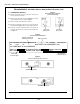
Figure 4
Low flame orifice replacement
Figure 2
Pilot orifice assembly
Figure 3
Main orifice and holder
Main orifice
Main orifice
holder
Main manifold tap
plug (leave in place)
Aluminum
tubing
T
o
b
u
rn
e
r
Low flame
orifice
F
ro
m
c
o
m
b
in
a
tio
n
g
a
s
c
o
n
tro
l v
a
lv
e
Solenoid valve
Pilot orifice
Pilot tap plug
Pilot tubing connector
SECTION 3 - SERVICING COMPONENTS
Appendix - Instructions for Service Kit 36856 - Gas Conversion Kit for
PS360EWB/WB70 with Midco Burner, Natural Gas to Propane, 1/98