
Microwave Oven User Manual


4
I. GAS OVEN SEQUENCE OF OPERATION
A. Electrical Supply
Gas heated ovens operate on 208/240V, single phase.
Standard incoming power configurations are:
1. 4-wire system (PS200 series, PS310/360 series,
PS570, PS570S) - 2 single phase 208/240V sup-
ply (hot) lines, 1 neutral and 1 ground.
2. 3-wire system (PS360WB70, PS360EWB, PS555,
PS570G, PS536) - 2 single phase 208/240V sup-
ply (hot) lines and 1 ground.
For all wiring configurations, the voltage when measured
from either hot line to neutral should never exceed 130V.
B. Door Switch
Closing the control cabinet door (or machinery com-
partment door, as appropriate for the oven model) will
close the door switch and allow the oven to operate.
Note that the electrical systems will still be live
if the switch is open, although the oven cannot
operate.
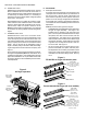
The door switch has a bypass position to enable ser-
vice operation with the door opened. When the door is
open, grasp the switch actuator and pull it out as far as
possible. This will close the door switch and permit
troubleshooting. Closing the control cabinet door will
reset the switch.
1. Closing the door switch permits a circuit to go
through a fuse (or circuit breaker, as appropriate
for the oven model) to one side of the conveyor
switch, blower motor switch, cooldown relay and
heat switch.
2. Closing the door switch permits a circuit to go
through the motor fuse (two 9A or 15A fuses per
motor).
C. Conveyor Switch
Closing the conveyor switch permits a circuit to go to
the Conveyor Speed Control Module, which:
1. Sends power to the gear motor (conveyor drive mo-
tor). The 120VAC signal to the Conveyor Speed
Control Module is rectified to a 90VDC signal which
is then sent to the gear motor.
2. Allows regulation of conveyor speed. Adjusting the
thumbwheel (or digital pushbutton display unit, as
appropriate) to the desired conveyor belt speed in-
structs the Conveyor Speed Control Module to regu-
late the output to the gear motor. This increases
or decreases the conveyor speed as necessary to
match the speed setting shown on the thumbwheel
or display unit.
D. Blower Switch
Closing the blower switch energizes:
1. The cooling (axial) fan(s).
2. The blower motor contactor (s).
Closing this contactor starts the blower motor(s). When
both blower motors are up to speed, centrifugal switches
located inside the blower motors (or air switches de-
tecting blower operation, as appropriate for the oven
model) will close, setting up the heat circuit.
3. The Temperature Controller.
E. Heat Switch
Closing the heat switch completes a circuit:
1. Through the heat switch.
2. Through the blower motor centrifugal switches (or
air switches, as appropriate for the oven model).
3. Through the high limit switch.
4. One circuit then goes to the:
a. Burner (L1).
b. Transformer (110V to 24V).
c. Motor relay coil. On a cold start the heater on
this relay takes about 30 seconds to warm up
before the relay will energize. This gives an
additional prepurge. The relay is not used on
ovens with 208/240V burner blower motors.
d. Burner blower motor. As the motor reaches full
operating speed, the centrifugal switch (or air
flow switch, as appropriate for the oven model)
closes and applies voltage to the burner con-
trol. This energizes the ignitor control spark
transformer and the pilot valve. The spark then
lights the pilot. The flame sensor proves the
presence of the pilot flame, and the ignitor con-
trol then shuts off the spark. At the same time,
the main burner valve is opened. The main
burner is then ignited.
If the pilot does not light within approximately
90 seconds, the oven will shut down.
The pilot and main gas valve will stay on (open)
as long as the heat switch is ON and the flame
is proven. If the flame goes out for any reason,
the pilot will try to light for 90 seconds, and
then go into automatic lockout. To relight the
pilot after it has gone into automatic lockout,
the burner
must be turned OFF for 5 minutes
and then turned ON again.
SECTION 1
SEQUENCE OF OPERATION
SECTION 1 - SEQUENCE OF OPERATION