
Microwave Oven User Manual


59
4
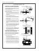
PS360 Series front-mounted thermocouple
inside the machinery compartment
These thermocouples are mounted in a tube that extends
diagonally up and into the plenum chamber. They are se-
cured in place by a set screw located on the mounting
tube, and by a bead of high-temperature silicone around
the end of the shaft.
The new thermocouple will be held in place in the same
manner, except that the silicone should be applied so that
it wraps around the edges of the thermocouples mounting
flange.
NOTE FOR HIGH LIMIT THERMOCOUPLES:
PS310/360 electric ovens have two thermocouples inside
the machinery compartment. One thermocouple is con-
nected to the temperature controller, while the other is
connected to the high limit control module.
The thermocouple supplied in this Kit is incompatible with
the early United Electric Type 54 and Type 55 high limit
control modules used on these ovens. If the oven is
equipped with one of these control modules, it will be
necessary to upgrade the control unit to the current
Watlow model (shown in Figure 6) before the thermo-
couple can be replaced. Service Kit 39733 includes all
parts and instructions needed for the conversion. Refer
to Service Bulletin MM-168 (5/7/99) for details.
1. Remove the silicone seal around the end of the thermo-
couple. Loosen the set screw.
2. Pull the thermocouple out of its mounting tube. Care-
fully thread the wiring out of the oven and discard the
thermocouple.
3. Check that the silicone has been removed completely
from the end of the mounting tube. Any remaining sili-
cone can interfere with the correct placement of the
new thermocouple.
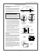
4. Insert the new thermocouple until its flange is seated
on the end of the mounting tube. See Figure 5.
5. Tighten the set screw until the thermocouple is secure
inside the tube. AVOID OVERTIGHTENING THE SET
SCREW TO PREVENT DAMAGE TO THE THERMO-
COUPLE.
6. Use high-temperature silicone to seal the flange to the
mounting tube, as shown in Figure 5. Check that all
holes and spaces are filled by the silicone. This not
only helps to hold the thermocouple in place, but pre-
vents heat from entering the machinery compartment.
7. Route the wiring for the new thermocouple through the
hole in the side of the electrical control box by using
the existing wiring bundle. Check that the leads are
clear of the ignition cable and all components.
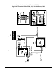
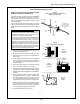
8. Connect the leads as shown in Figure 6.
Figure 5
Thermocouple Installation - PS360 Series
Machinery Compartment
Thermocouple
Mounting
tube
Set
screw
High-temperature
silicone wraps around
thermocouple flange
and onto mounting
tube
Plenum
wall
Figure 6
Thermocouple Wiring - PS360 Series
Digital
Temperature
Controller
Analog
Temperature
Controller
Red
White
Shielded
ground lead
RedWhite
Shielded
ground lead
High Limit
Control
Module
Shielded
ground lead
Red White
Appendix - Instructions for Service Kits 33984 and 33985 -
Oven Thermocouple Kit, 11/01
SECTION 3 - SERVICING COMPONENTS