
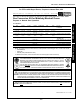
Microwave Oven User Manual


127
ENGLISH
3
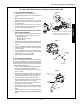
I. PREPARATION AND DISASSEMBLY
1. Turn off the electric power supply to the oven.
2. Turn off the gas supply at the service valve behind the
oven.
3. Open the machinery compartment door.
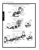
4. Open the union in the gas supply line. The union is
located on the inlet side of the combination gas control
valve. See Figure 1.
5. Unscrew the four hex screws that hold the venturi
mounting plate to the front of the burner. Remove the
gas train/venturi assembly from the oven.
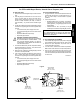
II. COMBINATION GAS CONTROL VALVE (SAFETY
REGULATOR) CONVERSION
1. Remove and discard the following components from the
combination gas control valve, as shown in Figure 2:
Regulator cap screw
Regulator adjustment screw
Regulator spring
2. Install the stainless steel kit-supplied regulator spring,
with the tapered end facing into the valve, as shown in
Figure 2.
3. Install the kit-supplied regulator adjustment screw.
Carefully adjust the screw until its top is flush with the
top of the regulator.
4. Turn the adjustment screw six complete turns in a
clockwise direction. This preliminary pressure setting
is approximately 3-1/2 W.C. (8.7mbar).
5. Install the silver kit-supplied cap screw.
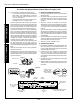
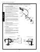
III. BYPASS ORIFICE CONVERSION
NOTE: Ovens are equipped with EITHER an on-off solenoid
valve with a separate bypass line, OR with a modulating gas
valve. Refer to the illustrations on Page 2. When installing
this Kit, the bypass orifice will only be changed if the oven
is equipped with a solenoid valve.
If the oven is equipped with a modulating gas valve, skip
ahead to Section IV, Pilot Orifice Conversion.
If the oven is equipped with a solenoid valve, continue on
to Step 1, below.
1. Unscrew the compression nuts at both ends of the
bypass tube, and slide them back and out of the way.
Then, remove and retain the tubing. See Figure 3.
2. Remove and discard the existing bypass orifice.
3. Slip the kit-supplied bypass orifice into the discharge
end of the bypass tube, as shown in Figure 3.
4. With the orifice in place, push the tube back into the
compression fittings until it bottoms.
5. While holding the tube in place, slide the compression
nuts into place. Tighten them to a snug fit with your
fingers.
6. Gently tighten the nuts one complete turn with a
wrench. DO NOT OVERTIGHTEN THE COMPRESSION
NUTS.
Figure 1
Gas pipe
union
PS570S gas train (with solenoid valve) shown.
Refer to the illustrations on Page 2 for
component placement for other oven models.
Hex
screws
Figure 2
Regulator
spring
Adjustment
screw
Cap screw
Figure 3
Bypass
tube
Bypass
orifice
Compression
nut
SECTION 3 - SERVICING COMPONENTS
Appendix - Instructions for All Gas Conversion Kits
for Ovens with Wayne Burner, Propane to Natural Gas, 8/00