
Microwave Oven User Manual

144
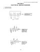
SECTION 3 - SERVICING COMPONENTS
C. PS555 ovens
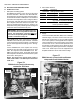
1. Description of heating system
All PS555 electric ovens use a variable pulse system
for heater activation.
In response to the millivolt signal from the thermocouple,
the temperature controller sends a 4-20mA signal to a
controller module. This module contains an amplifer
board and two solid state relays. The amplifier board
receives the 4-20mA signal and in turn activates the
relays. The relays then activate the heating elements.
The relays operate on a fixed cycle time. Within each
cycle, the relays activate the heating elements at 100%
for a length of time that is proportional to the signal
from the amplifier board.
When the oven is switched on, heat demand is at its
peak and the elements are activated for 100% of each
cycle. As the ovens temperature approaches the set
point, the relays reduce the length of time that the heat-
ers are activated wihin each cycle. After the oven is
fully preheated, the heaters are usually activated for
about 30% of each cycle. This system allows the ac-
tual oven temperature can remain constant, with NO
temperature swing.
IMPORTANT: The PS555 electric oven uses a
variable pulse system that is designed to emu-
late the PID gas operating mode. Because of
this, the temperature controller MUST be set
to the PID operating mode.
Temperature controller P/N 46837 (inc. with
Service Kit 47321) includes a dedicated vari-
able pulse mode intended for the PS536 elec-
tric oven. This mode is NOT used on the PS555
electric oven. If you are using controller P/N
46837, be sure to set the controller for the PID
operating mode.
Refer to Temperature Controller on Page 30.
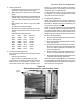
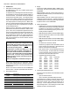
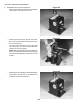
Heaters are arranged into four assemblies, each of
which contains three elements. Each pair of assem-
blies (left and right) share a controller and a 50A circuit
breaker block.
NOTE: All control wire used on this oven is AWM rated
at 221°F/105°C. DO NOT replace with lower rated wire.
3. Supply
Ovens have a 208V, 220-240V, 380V or 480VAC elec-
trical supply. The control current of the oven operates
at 208/240V.
208V and 240V ovens use a 3-wire system (4-wire in-
cluding the ground connection). The control circuit op-
erates at line voltage.
380V and 480V ovens use a 4-wire system (5-wire in-
cluding the ground connection). The 4th (neutral) wire
is utilized to split the incoming 3 phase legs and obtain
a separate control circuit at 208/240V.
2. Part number reference
Part No. Description
43337 Heating element assembly, 208V
44525 Heating element assembly, 230V
44526 Heating element assembly, 380V
44527 Heating element assembly, 480V
44914 Controller module, 208/230/240V ovens
44568 Controller module, 380/480V ovens
35018 Circuit breaker block, 50A, 3 pole
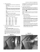
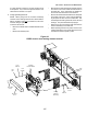
5. Checking the Heating Elements
The most common problems encountered with electric
heaters are:
Open or bad connections.
Open, shorted or grounded heating elements.
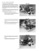
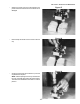
To troubleshoot the heating elements, disconnect all
leads at the terminal blocks on the back wall. Then,
check each element with a digital multimeter set to
Ohms (W). Correct ratings are shown in the table in
the preceding section. Zero reading on the ohm scale
indicates an open or shorted element.
4. Heater specifications
PS555 electric ovens use 12 heating elements in 4
assemblies (3 elements per assembly). Elements
CANNOT be removed from the assembly. If one
element is not functioning properly, the entire as-
sembly should be replaced.
208V elements are used for ovens with a 208V supply.
240 volt elements are used for ovens with a 220V,
230V or 240V supply.
380V elements are used for ovens with a 380V supply.
480V elements are used for ovens with a 416V or 480V
supply.
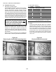
All heaters are connected in Delta.
Heaters are grouped into four assemblies, each of
which contains three elements. Elements CAN-
NOT be removed from the assembly.
Each element has a cold (unheated) end next to
the connecting leg. 12/0.3m leads are connected
to the cold ends for easy connection to the termi-
nal blocks on the back wall of the oven.
Individual element electrical data
Volts Watts Ohms Connection
208V 2667W 16.2W Parallel
220V 2241W 21.6W Parallel
230V 2449W 21.6W Parallel
240V 2667W 21.6W Parallel
380V 2667W 54.1W Parallel
416V 2003W 86.4W Parallel
480V 2667W 86.4W Parallel