
Microwave Oven User Manual

38
Page 6 of 10
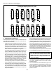
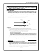
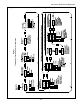
Jumper Setting
Loosen the Phillips screw at the bottom center of the faceplate. Then, pull the controller out of its sleeve.
Next, access the jumper shown in Figure 6. This jumper affects the signal that is output from Terminals
15 and 16.
The jumper MUST be set to the correct position for proper operation of the controller.
Figure 6
Jumper is set to the W1
position for gas ovens with
modulating gas system
Jumper is set to the W2
position for electric ovens
with variable pulse system
For gas ovens equipped with the modulating gas system, the jumper must be set to the
W1 position.
This instructs the controller to send a variable-current 4-20 mA signal from Terminals 15 and 16 to
the amplifier board. The board converts this to a 0-24VDC signal which is sent to the modulating
valve. The valve regulates the gas flow according to the need for heat to maintain the set point.
For gas ovens, you should always check inside the machinery compartment to see whether a modu-
lating valve is present in the unit before setting this jumper.
For electric ovens equipped with the variable pulse system, the jumper must be set to the
W2 position.
This instructs the controller to send a constant-current, pulsed 20VDC signal to the relay. Once per
second, the signal pulses on proportional to the need for heat to maintain the set point.
As of 1/02, only the PS536 Electric oven uses the variable pulse system. Other oven models equipped
with this system will be announced by Middleby as they become available.
For all other ovens - gas or electric - that use the on-off system, the jumper may be set to
either position.
After the jumper has been properly set, replace the controller into its sleeve and tighten the screw.
CAUTION
If the jumper is incorrectly set, the oven will be unable to properly maintain temperature. In addi-
tion, DAMAGE MAY OCCUR TO THE CONTROLLER AND OTHER OVEN COMPONENTS.
Always make sure that the jumper is correctly set BEFORE restoring power to the oven!
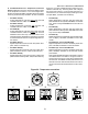
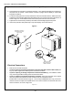
Programming
1. Restore electrical power to the oven.
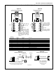
2. Refer to Figure 7. Set the following options,
according to the customers preferences:
Set Point locked or unlocked
Degrees Fahrenheit or Celsius
Set Point or Actual Temperature display
3. Set the controller to PID or On-Off operating
mode. Choose the PID mode for BOTH gas
ovens with the modulating system AND for elec-
tric ovens with the variable pulse system.
4. Adjust the Set Point according to the
customers specifications.
5. If the PID operating mode was chosen, per-
form an Auto-Tune calibration as per the in-
structions in Figure 7.
6. Check that the customer is familiar with the
operation of the controller. The last page of
these instructions includes an operating guide
for the controller. Remove this page and leave
it with the customer for future reference.
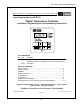
SECTION 3 - SERVICING COMPONENTS
Appendix - Instructions for Service Kit 47321 - Digital Temperature Controller Kit, 2/02