P/N 44827 Rev. B V1 12/00 página 57 ESPAÑOL page 29 FRANÇAIS page 1 ENGLISH PS555 Gas & Electric Domestic & Std. Export ENGLISH/French/Spanish PS555 Gas and Electric Ovens Model: Combinations: PS555 Single Oven Double Oven (Two-Stack) Triple Oven (Three-Stack) Quad Oven (Four-Stack) OWNER'S OPERATING AND INSTALLATION MANUAL PS555 GAS © 2000 Middleby Marshall, Inc. is a registered trademark of Middleby Marshall, Inc. All rights reserved.
NOTICE: This Owner's Operating and Installation Manual should be given to the user. The operator of the oven should be familiar with the functions and operation of the oven. This manual must be kept in a prominent, easily reachable location near the oven. ENGLISH Gas ovens are designed for use with EITHER natural gas OR liquid propane gas, as specified on the serial plate.
TABLE OF CONTENTS page page V. FINAL ASSEMBLY ................................................... 10 I. OVEN USES ............................................................. 4 VI. ELECTRICAL SUPPLY ........................................... 10 II. OVEN COMPONENTS ............................................. 4 A. Additional Information - Gas Ovens ................ 10 A. Conveyor Drive Motor ....................................... 4 B. Additional Information - Electric Ovens .......... 10 B.
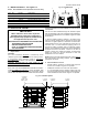
SECTION 1 - DESCRIPTION I. ENGLISH OVEN USES K. PS555 Ovens can be used to bake and/or cook a wide variety of food products, such as pizza, pizza-type products, cookies, sandwiches and others. Not Shown: Control Panel: Location of the operating controls for the oven. Refer to Section 3, Operation, for details. L. Gas Burner (gas ovens) or Heating Elements (electric ovens): Heat air, which is then projected to the air fingers by the blowers. II. OVEN COMPONENTS - see Figure 1-1. A.
Main Blower Voltage Control Circuit Voltage Phase Freq Current Draw Poles Wires 208-240V 120V conveyor speed controller (w/transformer); all other control circuits 208/240V 1 Ph 50/60Hz 12A 2 Pole 3 Wire (2 hot, 1 gd) Table 1-5: Gas orifice and pressure specifications for gas ovens (per oven cavity) Gas Type Natural Propane Main Orifice I.D. 0.228 (5.79mm) Pilot Orifice I.D. 0.028 (0.71mm) Supply (Inlet) Pressure 6-12 W.C. (14.9-29.9mbar) Orifice (Manifold) Pressure 3.5 W.C. (8.
SECTION 2 - INSTALLATION Fig. 2-1 - Base Pad Kit 1 9 ENGLISH 8 2 7 3 13 11 4 14 6 10 5 I. 12 BASE PAD KIT - see Figure 2-1 NOTE: One Base Pad Kit is required for each Single, Double, Triple, or Quad Oven installation. Quantity Doubleoven Doubleoven w/10"legs w/15"legs Item Singleoven Tripleoven Quadoven Part No.
SECTION 2 - INSTALLATION II. INSTALLATION KIT - see Figure 2-2 NOTE: One Installation Kit is required for each oven cavity. Qty. Part No. 1 1 35900-0148 2 1 35000-1103 3 1 44827 4 1 1002040 Description 4 Conveyor Rear Stop 2 3 Conveyor End Stop ENGLISH Item Fig. 2-2 - Installation Kit 5 1 Owner's Operating & Installation Manual Authorized Service Agency Listing ADDITIONAL COMPONENTS FOR GAS OVENS: 5 1 33120-0053 Gas Pipe Nipple III.
SECTION 2 - INSTALLATION IV. ASSEMBLY A. Figure 2-4 - Legs and Casters for Single or Double Oven Base Pad, Legs, Casters, and Stacking ENGLISH 1. Install the top panels in place on the top oven cavity. Follow the instructions provided with the top panels. 1/2" flat washer 2a. Legs/Casters Installation - Single and Double Ovens Install one leg extension to each corner of the base pad using the 1/2"-13x1-1/4" bolts, 1/2" flat washers, and 1/2" lockwashers supplied in the Installation Kit.
SECTION 2 - INSTALLATION Lift the conveyor and position it in the oven as shown in Figure 2-9. 2. Continue moving the conveyor into the oven until the frame protrudes equally from each end of the oven (about 18"/ 457mm). 3. Check that the retainers located on the underside of the conveyor frame rest firmly against the lower end plugs, as shown in Figure 2-9. 4.
SECTION 2 - INSTALLATION V. FINAL ASSEMBLY ENGLISH 1. Install the crumb trays underneath the conveyor as shown in Figure 2-12. First, place the inside edge of the tray onto the retainer (shown in Figure 2-9). Then, swing the outside edge of the tray up and into place. 2. Press the conveyor end stop and rear stop down over the edge of the conveyor frame. See Figure 1-1 (in Section 1, Description).
SECTION 2 - INSTALLATION Figure 2-13 - Utility Connection Locations for Gas Ovens ENGLISH Electrical Junction Box One per oven cavity Gas Inlet One per Single, Double, Triple, or Quad Oven Figure 2-14 - Utility Connection Locations for Electric Ovens 2" (51mm) cutcout for electrical supply VII. GAS SUPPLY CAUTION 3. If incoming pressure is over 14 W.C. (35mbar), a separate regulator MUST be installed in the line BEFORE the individual shutoff valve for the oven.
SECTION 2 - INSTALLATION B. Connection plies with the Standard for Quick-Disconnect Devices for Use With Gas Fuel, ANSI Z21.41 (in U.S.A.), or, if applicable, QuickDisconnect Devices for Use With Gas Fuel, CAN1-6.9 (in Canada). Check the ovens gas supply requirements before making the gas utility connection. Gas supply requirements are listed on the ovens serial plate and in Table 1-3, Gas Orifice and Pressure Specifications (in Section 1, Description). C.
SECTION 3 - OPERATION I. LOCATION AND DESCRIPTION OF CONTROLS E. D. Digital Temperature Conveyor Speed ( ) controller ( ( ) controller(s) A. B. C. "BLOWER" "HEAT" "CONVEYOR" ) switch A. "BLOWER" Switch: Turns the blowers and cooling fans on and off. The HEAT Switch has no effect unless the BLOWER Switch is in the ON position. B. "HEAT" Switch: Allows the burner or heating elements, as appropriate for the oven model, to activate.
SECTION 3 - OPERATION II. NORMAL OPERATION - STEP-BY-STEP A. DAILY STARTUP PROCEDURE 1. Check that the circuit breaker/fused disconnect is in the on position. Check that the window is closed. ENGLISH 2. Turn the "BLOWER" ( ) switch to the ON ("I") position. 3. Turn the "CONVEYOR" ) switch to the ON ( ("I") position. 4. 5. 6. Press the Set Point and Unlock keys at the same time. Wait for the "SET PT" light to turn on.
SECTION 3 - OPERATION "SP LOCK" Light Lights when the set point is locked out from changes. This setting can only be changed by service personnel. Display Shows the Set Point or the Actual Temperature in degrees Fahrenheit (F) or Celsius (C). "HEAT ON" Light Lights when the burner or heating elements, as appropriate for the oven model, are in operation. "SET PT" (setpoint) Light Lights when the set point is shown in the display.
SECTION 3 - OPERATION IV. QUICK REFERENCE: SYMPTOM TROUBLESHOOTING PROBLEM SOLUTION ENGLISH The oven temperature exceeded 650°F (343°C), and the burner or heating elements were automatically shut down. Follow the procedures under Daily Shutdown Procedures in this section to shut down the oven. Contact your Middleby Marshall Authorized Service Agent to determine and correct the cause of the condition to prevent damage to the oven.
SECTION 4 - MAINTENANCE WARNING 1. 2. 3. Switch off the oven and allow it to cool. Do NOT service the oven while it is warm. Turn off the electric supply circuit breaker(s) and disconnect the electric supply to the oven. If it is necessary to move the oven for cleaning or servicing, disconnect the gas supply connection before moving the oven. When all cleaning and servicing is complete: 1. If the oven was moved for servicing, return the oven to its original location. 2.
SECTION 4 - MAINTENANCE II. MAINTENANCE - MONTHLY Figure 4-3 - Removing Air Fingers and Plates NOTE When removing the conveyor, refer to Figure 2-9 (in Section 2, Installation). ENGLISH A. Check that the oven is cool and the power is disconnected, as described in the warning at the beginning of this Section. B. Remove the crumb trays and drive motor shroud from the oven. C. Lift the drive end of the conveyor slightly, and push it forward into the oven.
SECTION 4 - MAINTENANCE III. MAINTENANCE - EVERY 3 MONTHS Check that the oven is cool and the power is disconnected, as described in the warning at the beginning of this Section. B. Vacuum both of the blower motors, and their surrounding compartments, using a shop vacuum. 17. After the belt tension is properly adjusted, tighten the hex jam nuts (shown in Figure 4-5) against the idler shaft bracket. This prevents the conveyor from being over-tightened. C. Tighten all electrical control terminal screws.
SECTION 4 - MAINTENANCE E. Figure 4-8 - Rear Shrouds and Guard Plates Blower Belts 1. To gain access to each blower belt compartment, remove the four screws shown in Figure 4-8. Then, lift the rear shroud off its hangers. End shroud screws (3 per shroud - 1 rear, 2 front) ENGLISH If access to the blower motors is required, remove the three mounting screws (two on the front of each shroud, one on the rear). Then, lift the end shroud straight up and off its hangers.
SECTION 4 - MAINTENANCE V. KEY SPARE PARTS KIT - Available separately. See Figure 4-11. Gas Ovens Item Qty. B. Part No. 1 1 36939 2 1 27384-0008 3 2 22450-0052 4 1 37337 5 1 27170-0263 6 1 33984 7 1 97525 8 1 27381-0069 9 1 39530 10 1 42810-0114 11 1 38811 12 1 41647 Description Electric Ovens Item Qty. Part No.
ENGLISH Fig. 5-1 Schematic, PS555 Gas Oven, 208/240V, 60Hz, 1 Ph CIRCUIT BREAKER TEMP (T2) HIGH LIMIT TEMP (T2) RESET SWITCH LIGHT SIGNAL CONDITIONER BURNER BLOWER MOTOR COOLING FAN DOOR SWITCH 22 MOTORS DOOR SWITCH DOOR SWITCH BLOWER CONVEYOR CONTROL COOLING FAN TRANSFORMER 230V PRI. 120V SEC. 0.2 KVA COOLDOWN SWITCH (T1) TEMPERATURE CONTROL (T1) MODULATING GAS VALVE IGNITOR PILOT SENSOR IGNITION MODULE TRANSFORMER 240V PRI. 24V SEC. 0.
Fig.
ENGLISH TEMP (T2) RESET SWITCH TEMP (T2) HIGH LIMIT SECTION 5 - ELECTRICAL WIRING DIAGRAMS Fig. 5-3 Schematic, PS555 Electric Oven, 208V or 240V, 60Hz, 3 Ph TEMP (T2) RESET SWITCH LIGHT SSR COOLING FAN COOLDOWN SWITCH COOLING FAN DOOR SWITCH DOOR SWITCH DOOR SWITCH 24 CONVEYOR SWITCH COOLING FAN HALL EFFECT SENSORS TRANSFORMER 230V PRI. 120V SEC. 0.
Fig.
page 1 página 57 page 29 ENGLISH ESPAÑOL FRANÇAIS TEMP (T2) RESET SWITCH TEMP (T2) HIGH LIMIT SECTION 5 - ELECTRICAL WIRING DIAGRAMS Fig. 5-5 Schematic, PS555 Electric Oven, 380V or 480V, 60Hz, 3 Ph TEMP (T2) RESET SWITCH LIGHT SSR COOLING FAN DOOR SWITCH DOOR SWITCH DOOR SWITCH COOLDOWN SWITCH COOLING FAN 26 CONVEYOR SWITCH COOLING FAN HALL EFFECT SENSORS TRANSFORMER 230V PRI. 120V SEC. 0.
Fig.
ENGLISH page 1 FRANÇAIS page 29 ESPAÑOL página 57 Middleby Cooking Systems Group 1400 Toastmaster Drive Elgin, IL 60120 USA (847)741-3300 FAX (847)741-4406 24-Hour Service Hotline: 1-(800)-238-8444 www.middleby.