PS640 Series Electric Domestic & Std. Export ENGLISH P/N 60614 October 2007 PS640 Series Electric Ovens Model: Combinations: • • • • PS640E Electric Single Oven Double Oven (Two-Stack) Triple Oven (Three-Stack) OWNER'S OPERATING AND INSTALLATION MANUAL for domestic and standard export ovens ©2007 Middleby Marshall Inc. is a registered trademark of Middleby Marshall, Inc. All rights reserved.
NOTICE: This Owner's Operating and Installation Manual should be given to the user. The operator of the oven should be familiar with the functions and operation of the oven. This manual must be kept in a prominent, easily reachable location near the oven. It is suggested to obtain a service contract with a Middleby Marshall Authorized Service Agent. WARNING FOR YOUR SAFETY, DO NOT STORE OR USE GASOLINE OR OTHER FLAMMABLE VAPORS AND LIQUIDS IN THE VICINITY OF THIS OR ANY OTHER APPLIANCE.
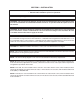
Model No. Modéle No. Serial No. Serié No. Installation Date Date d'installation MIDDLEBY MARSHALL NO QUIBBLE LIMITED WARRANTY (U.S.A. ONLY) MIDDLEBY MARSHALL INC. OVEN LIMITED WARRANTY (Non U.S.A.) The Seller warrants equipment manufactured by it to be free from defects in material and workmanship for which it is responsible. The Seller’s obligation under this warranty shall be limited to replacing or repairing, at Seller’s option, without charge, F.O.B.
TABLE OF CONTENTS Page Page SECTION 3 – OPERATION .............................................. 15 I. LOCATION AND DESCRIPTION OF CONTROLS 15 II. NORMAL OPERATION, STEP-BY-STEP ................ 16 A. Main Screen ................................................ 16 B. Daily Startup Procedure .............................. 17 C. Daily Shutdown Procedure ......................... 17 III. QUICK REFERENCE: TROUBLESHOOTING ...... 18 IV. SCREEN ALERTS .................................................
SECTION 1 – DESCRIPTION Figure 1-1. Oven Components I. OVEN USES PS640 Series Ovens can be used to bake and/or cook a wide variety of food products, such as pizza, pizza –type products, cookies, sandwiches and others. E D J I II. OVEN COMPONENTS – see Figure 1-1. A. Conveyor Drive Motor: Moves the conveyor. B. Crumb Pans: Catch crumbs and other materials that drop through the conveyor belt. One crumb pan is located at each end of the conveyor. C. Conveyor: Moves the food product through the oven.
I.
SECTION 2 – INSTALLATION WARNING – After any conversions, readjustments, or service work on the oven: • Check that the ventilation system is in operation. WARNING - Keep the appliance area free and clear of combustibles. WARNING – The oven must be installed on an even (level) non-flammable flooring and any adjacent walls must be non-flammable. Recommended minimum clearances are specified in the Description section of this manual.
PS640 OVEN INSTALLATION REQUIRED KITS AND EQUIPMENT PS640 Electric Oven Installation Kit TYPE OF INSTALLATION P/N47810-0008 PS640 Single Oven Option Base w/ 15″ Legs, Casters & Top Kit P/N59720 1 1 PS640 Single Electric Oven PS640 Double Electric Oven 2 PS640 Triple Electric Oven 3 PS640 DoubleOven OptionBase w/ 6″ Legs, Casters & Top Kit P/N59725 PS640 TripleOven OptionBase w/ Casters& Top Kit P/N59726 1 1 PARTS LIST FOR SERIES PS640 ELECTRIC OVEN INSTALLATION KIT P/N 47810-0008 (Two required
Figure 2-2. Model PS640 Single Oven Option Base with Legs and Top 1 8 HARDWARE BAG 5, 6, 7, 10 & 11 3 4 2 9 PARTS LIST FOR PS640 SERIES SINGLE OVEN OPTION - BASE w/15″″ LEGS & TOP P/N 59720 ITEM NO. QTY PART NO.
Figure 2-3. Model PS640 Double Oven Option Base with Legs and Top 1 8 HARDWARE BAG 5, 6, 7, 10 & 11 3 4 2 9 PARTS LIST FOR PS640 SERIES DOUBLE OVEN OPTION - BASE w/6″″ LEGS & TOP P/N 59725 ITEM NO. QTY PART NO.
Figure 2-4. Model PS640 Triple Oven Option Base with Outriggers and Top 1 15 HARDWARE BAG 7, 8, 9, 10, 11, 12, 13, 14, & 17 3 5 4 6 2 16 PARTS LIST FOR PS640 SERIES TRIPLE OVEN OPTION - BASE w/CASTERS & TOP P/N 59726 ITEM NO. 1 QTY 1 PART NO.
B. Recommendations III. VENTILATION SYSTEM NOTE THAT THE HOOD DIMENSIONS SHOWN IN FIGURE 2-5 ARE RECOMMENDATIONS ONLY. LOCAL, NATIONAL AND INTERNATIONAL CODES MUST BE FOLLOWED WHEN INSTALLING THE VENTILATION SYSTEM. ANY APPLICABLE CODES SUPERSEDE THE RECOMMENDATIONS SHOWN IN THIS MANUAL. IMPORTANT Where national or local codes require the installation of fire suppression equipment or other supplementary equipment, DO NOT mount the equipment directly to the oven.
Figure 2-6. Leg extension and casters installation IV. ASSEMBLY A. Top Panel and Base Pad Assembly 1. Install the four leg extensions onto the base pad using the 3/8″-16 × 1″ screws, 3/8″ flat washers, and 3/8″ lockwashers supplied in the Base Pad Kit. See Figure 2-6. Check that the finished sides of each leg extension face OUTWARDS. One rear leg should be attached using three 3/8″-16 × 1″ screws and the 3/4″ eyebolt, as shown in Figure 2-6.
C. Restraint Cable Installation NOTE: DO NOT install top panel onto double or triple ovens until AFTER stacking the oven cavities. See Part B, Stacking. For single ovens, skip ahead to Part C, Restraint Cable Installation. Because the oven is equipped with casters, a restraint cable assembly must be installed to limit the movement of the appliance without depending on the connector and the quick disconnect device or its associated piping.
D. Conveyor Installation 1. 2. Figure 2-13. Conveyor placement Unfold the conveyor as shown in Figure 2-12. Then, begin to slide the conveyor into the end of the oven. The conveyor can only be installed from the end of the oven with the drive motor. Crumb tray support bracket Continue moving the conveyor into the oven until the frame protrudes equally from each end of the oven.
5. If it is necessary to add or remove conveyor links to achieve the correct tension, OR if it is necessary to reverse the conveyor belt for correct orientation, the belt will need to be removed from the conveyor frame. If this is necessary, perform the following procedure: CONVEYOR BELT REVERSAL Conveyor belt reversal consists of three steps: • Remove the conveyor assembly from the oven and place it flat on the floor. 1. Physically reversing the conveyor belt. 2.
III. ELECTRICAL CONNECTION INFORMATION FOR PS640E-SERIES OVENS. IV. ELECTRIC SUPPLY FOR ELECTRICALLY HEATED OVENS Power requirements for electrically heated ovens are usually 208 - 240VAC, 3-phase, 4-wire (3 ‘hot’, 1 ground), although ovens built for export can have power requirements of 380VAC and 480VAC. (These ovens have a 5-wire system.) A 2″ (51mm) diameter cutout/hole in the back of the machinery compartment provides access for the electrical supply connections.
UTILITY ROUGH-IN DIMENSIONS AND POSITIONING FOR PS640-SERIES OVENS WARNING DO NOT USE CONDUIT FOR GROUND CONNECTION. To Oven CAUTION IT IS RECOMMENDED THAT THE OVEN BE PLACED UNDER A VENTILATION HOOD FOR ADEQUATE AIR SUPPLY AND VENTILATION. To Oven ELECTRIC SUPPLY TO BE PROVIDED BY CUSTOMER Suggested dimensions are shown; utility code requirements supersede any factors shown. CIRCUIT BREAKER Figure 2-19.
SECTION 3 - OPERATION C. Temperature Control Display E. Message Bar Increase Decrease A. Main On/Off Button B. Conveyor Time Setting D. TEMP Set Right Left LOCATION AND DESCRIPTION OF CONTROLS A. Main On/Off Button C. Temperature Control/Display Turns all oven functions on or off. If the oven is below the set point, it will rise to the set point and turn the conveyor on. If it is turned off and the oven is above 200° F, the blowers will remain on until the oven drops below 200° F.
NORMAL OPERATION - STEP-BY-STEP 2. A. Main Screen 1. When the unit has been “OFF” for more than 1 minute the controller will display the screen saver, as shown in Figure 3-1. To start operation, push the “Enter/Reset” button. The controller will display the “OFF” screen, as shown in Figure 3-2. Push the “ON/OFF” button to start the oven. The controller will display the screen, as shown in Figure 3-3.
4. To change the conveyor belt speed, push the “TIME” button. The controller will display the screen, shown in ←” Figure 3-5. To change the minute setting, push the “← arrow button. Then push either the “↑” arrow or “↓” arrow buttons to increase or decrease the time accordingly. To change the second setting, push the “→” arrow button. Then push either the “↑” arrow or “↓” arrow buttons to increase or decrease the time accordingly. When the proper times are entered, push the “ENTER/RESET” button.
III. QUICK REFERENCE: TROUBLESHOOTING SYMPTOM PROBLEM SOLUTION Oven will not turn On. No electrical power • Check that the circuit breaker/fused disconnect is on. Make sure the emergenct stop button is on. Oven will not heat. Faulty contactor • Replace contactor. Faulty heater element • Replace element. Oven is operating, but little or no air is coming from the fingers. Air fingers may be assembled incorrectly after cleaning. • Turn oven off, and allow to cool. Reassemble fingers correctly.
SECTION 4 - MAINTENANCE WARNING Before ANY cleaning or servicing of the oven, perform the following procedure: 1. Switch off the oven and allow it to cool. Do NOT service the oven while it is warm. 2. Turn off the electric supply circuit breaker(s) and disconnect the electric supply to the oven. When all cleaning and servicing is complete: 1. If the oven was moved for servicing, return the oven to its original location. 2.
Figure 4-2. Removing Air Fingers and Plates II. MAINTENANCE – MONTHLY NOTE: When removing the conveyor, refer to Figure 2-12 (in Section 2, Installation). A. Check that the oven is cool and the power is disconnected, as described in the warning at the beginning of this Section. B. Remove the crumb trays from the oven. C. Lift the drive end of the conveyor slightly, and push it forward into the oven. This removes the tension from the drive chain. Then, remove the drive chain from the conveyor sprocket.
III. MAINTENANCE – EVERY 3 MONTHS A. Check that the oven is cool and the power is disconnected, as described in the warning at the beginning of this Section. B. Vacuum both of the blower mounts, and their surrounding compartments, using a shop vacuum. 8. Reassemble the idler shaft into the conveyor. Make sure that the bronze washer is in place between the two sections of the shaft. See Figure 4-4. 9. Replace the conveyor adjustment screws as shown in Figure 4-4.
Figure 4-7. Rear panel access Figure 4-6. Disassembling the drive shaft Remove eight (8) screws to remove rear panel Bearings (2 total) Blower belt Blower motor Loosen four (4) screws to adjust motor position and belt tension IV. MAINTENANCE - EVERY 6 MONTHS E. Blower Belt 1. Remove the eight screws shown in Figure 4-7. Then, remove the rear panel from the oven. 2. Check the blower belt for the proper 1/4″ (6mm) deflection at the center, and for cracking or excessive wear. See Figure 4-7.
V. KEY SPARE PARTS – Available separately. See Figure 4-8. 1 2 3 4 5 8 11, 12 6 9 7 10 18 17 13, 14, 15, 16 23 22 Figure 4-8. Key Spare Parts ITEM QTY. P/N DESCRIPTION 1 1 60191 DIGITAL DISPLAY, PROGRAMMED 2 3 4 5 6 7 8 9 10 11 12 13 14 15 16 17 18 19 20 21 22 1 1 1 1 1 1 1 1 1 2 2 1 1 1 1 1 1 1 1 1 2 58920 58679 60196 59668 57288 33983 51399 97525 50610 44914 44568 59942 60197 60198 50589 60091 60638 60683 58668 58669 59132 CONVEYOR DRIVE MOTOR W/PICKUP ASSY.
SECTION 5 TROUBLESHOOTING PROBLEM: OVEN BLOWER AND CONVEYOR OPERATE, YET THE OVEN IS NOT HEATING PROBLEM: PRODUCTS ARE OVERCOOKED OR UNDERCOOKED Check for correct setting of conveyor speed control. Check for correct setting on temperature controller. Reset the temperature controller to a new setting (above 200°F), after turning the BLOWER switch to off for 30 seconds. Set the conveyor speed control at correct setting. Turn temperature control to correct setting. Start the oven again.
Middleby-Marshall Model Number E208-240 Volt 50/60 Hz, 3 Phase 25 60227 Rev.
26 Middleby-Marshall Model Number E380-480 Volt 50/60 Hz, 3 Phase 60231 Rev.
NOTES 27
WARNING Improper installation, adjustment, alteration, service or maintenance can cause property damage, injury or death. Read the installation, operating and maintenance instructions thoroughly before installing or servicing this equipment. NOTICE During the warranty period, ALL parts replacement and servicing should be performed by your Middleby Marshall Authorized Service Agent. Service that is performed by parties other than your Middleby Marshall Authorized Service Agent may void your warranty.