PS740 Series Gas Domestic & Std. Export ENGLISH P/N 60250 May, 2009 Rev. D PS740 Series Gas Ovens Model: Combinations: • • • • PS740G Gas Single Oven Double Oven (Two-Stack) Triple Oven (Three-Stack) OWNER'S OPERATING AND INSTALLATION MANUAL for domestic and standard export ovens ©2007 Middleby Marshall Inc. is a registered trademark of Middleby Marshall, Inc. All rights reserved.
NOTICE: This Owner's Operating and Installation Manual should be given to the user. The operator of the oven should be familiar with the functions and operation of the oven. This manual must be kept in a prominent, easily reachable location near the oven. Ovens are shipped from the factory configured for use with natural gas. If permitted by local, national and international codes, at the time of installation the oven may be converted to propane gas operation.
Model No. Modéle No. Serial No. Serié No. Installation Date Date d'installation MIDDLEBY MARSHALL NO QUIBBLE LIMITED WARRANTY (U.S.A. ONLY) MIDDLEBY MARSHALL INC. OVEN LIMITED WARRANTY (Non U.S.A.) The Seller warrants equipment manufactured by it to be free from defects in material and workmanship for which it is responsible. The Seller’s obligation under this warranty shall be limited to replacing or repairing, at Seller’s option, without charge, F.O.B.
TABLE OF CONTENTS Page Page SECTION 1 – DESCRIPTION ............................................ 1 I. OVEN USES ............................................................ 1 II. OVEN COMPONENTS ............................................ 1 A. Conveyor Motor Drive ................................... 1 B. Crumb Pans .................................................. 1 C. Conveyor ....................................................... 1 D. End Plugs ......................................................
SECTION 1 – DESCRIPTION Figure 1-1. Oven Components I. OVEN USES PS740 Series Ovens can be used to bake and/or cook a wide variety of food products, such as pizza, pizza –type products, cookies, sandwiches and others. E D J I G II. OVEN COMPONENTS – see Figure 1-1. A. Conveyor Drive Motor: Moves the conveyor. B. Crumb Pans: Catch crumbs and other materials that drop through the conveyor belt. One crumb pan is located at each end of the conveyor. C.
I.
SECTION 2 – INSTALLATION WARNING – After any conversions, readjustments, or service work on the oven: • Perform a gas leak test. • Test for proper combustion and gas supply. • Test for correct air supply, particularly to the • Check that the ventilation system is in operation. burner blower. WARNING - Keep the appliance area free and clear of combustibles. WARNING – The oven must be installed on an even (level) non-flammable flooring and any adjacent walls must be non-flammable.
PS740 24″″ OVEN INSTALLATION REQUIRED KITS AND EQUIPMENT PS740 Gas Oven Installation Kit P/N61452 PS740 Single Oven Option Base w/ 15″ Legs, Casters & Top Kit P/N61123 PS740 Single Gas Oven 1 1 PS740 Double Gas Oven 2 PS740 Triple Gas Oven 3 TYPE OF INSTALLATION PS740 DoubleOven OptionBase w/ 6″ Legs, Casters & Top Kit P/N61457 PS740 TripleOven OptionBase w/ Casters& Top Kit P/N61458 1 1 PARTS LIST FOR SERIES PS740 GAS OVEN INSTALLATION KIT P/N 61452 (Two required for double oven) (Three requi
PS740 OVEN INSTALLATION REQUIRED KITS AND EQUIPMENT PS740 Gas Oven Installation Kit P/N61033 PS740 Single Oven Option Base w/ 15″ Legs, Casters & Top Kit P/N59720 PS740 Single Gas Oven 1 1 PS740 Double Gas Oven 2 PS740 Triple Gas Oven 3 TYPE OF INSTALLATION PS740 DoubleOven OptionBase w/ 6″ Legs, Casters & Top Kit P/N59725 PS740 TripleOven OptionBase w/ Casters& Top Kit P/N59726 1 1 PARTS LIST FOR SERIES PS740 GAS OVEN INSTALLATION KIT P/N 61033 (Two required for double oven) (Three required f
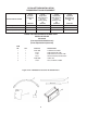
Figure 2-2A. Model PS740 24″″ Single Oven Option Base with Legs and Top 1 8 HARD WARE BA G 5, 6, 7, 10 & 11 3 4 2 9 12 PARTS LIST FOR PS740 SERIES 24″″ SINGLE OVEN OPTION - BASE w/15″″ LEGS & TOP P/N 61123 ITEM NO. QTY PART NO.
Figure 2-2B. Model PS740 32″″ Single Oven Option Base with Legs and Top 1 8 HARD WARE BA G 5, 6, 7, 10 & 11 3 4 2 9 12 PARTS LIST FOR PS740 SERIES 32″″ SINGLE OVEN OPTION - BASE w/15″″ LEGS & TOP P/N 59720 ITEM NO. QTY PART NO.
Figure 2-3A. Model PS740 24″″ Double Oven Option Base with Legs and Top 1 8 HARD WARE BA G 5, 6, 7, 10 & 11 3 4 2 9 12 PARTS LIST FOR PS740 SERIES 24″″ DOUBLE OVEN OPTION - BASE w/6″″ LEGS & TOP P/N 61457 ITEM NO. QTY PART NO.
Figure 2-3B. Model PS740 32″″ Double Oven Option Base with Legs and Top 1 8 HARD WARE BA G 5, 6, 7, 10 & 11 3 4 2 9 12 PARTS LIST FOR PS740 SERIES 32″″ DOUBLE OVEN OPTION - BASE w/6″″ LEGS & TOP P/N 59725 ITEM NO. QTY PART NO.
Figure 2-4A. Model PS740 24″″ Triple Oven Option Base with Outriggers and Top 1 15 HARDWARE BAG 7, 8, 9, 10, 11, 12, 13, 14, & 17 3 5 4 6 2 16 PARTS LIST FOR PS740 SERIES 24″″ TRIPLE OVEN OPTION - BASE w/CASTERS & TOP P/N 61458 ITEM NO. 1 QTY 1 PART NO.
Figure 2-4B. Model PS740 32″″ Triple Oven Option Base with Outriggers and Top 1 15 HARDWARE BAG 7, 8, 9, 10, 11, 12, 13, 14, & 17 3 5 4 6 2 16 PARTS LIST FOR PS740 SERIES 32″″ TRIPLE OVEN OPTION - BASE w/CASTERS & TOP P/N 59726 ITEM NO. 1 QTY 1 PART NO.
B. Recommendations III. VENTILATION SYSTEM NOTE THAT THE HOOD DIMENSIONS SHOWN IN FIGURE 2-5 ARE RECOMMENDATIONS ONLY. LOCAL, NATIONAL AND INTERNATIONAL CODES MUST BE FOLLOWED WHEN INSTALLING THE VENTILATION SYSTEM. ANY APPLICABLE CODES SUPERSEDE THE RECOMMENDATIONS SHOWN IN THIS MANUAL. IN AUSTRALIA COMPLIANCE TO REGULATIONS AS5601/AG601 IS MANDATORY.
Figure 2-6. Leg extension and casters installation IV. ASSEMBLY A. Top Panel and Base Pad Assembly 1. Install the four leg extensions onto the base pad using the 3/8″-16 × 1″ screws, 3/8″ flat washers, and 3/8″ lockwashers supplied in the Base Pad Kit. See Figure 2-6. Check that the finished sides of each leg extension face OUTWARDS. One rear leg should be attached using three 3/8″-16 × 1″ screws and the 3/4″ eyebolt, as shown in Figure 2-6.
C. Restraint Cable Installation NOTE: DO NOT install top panel onto double or triple ovens until AFTER stacking the oven cavities. See Part B, Stacking. For single ovens, skip ahead to Part C, Restraint Cable Installation. Because the oven is equipped with casters, a restraint cable assembly must be installed to limit the movement of the appliance without depending on the connector and the quick disconnect device or its associated piping.
D. Conveyor Installation 1. 2. Figure 2-13. Conveyor placement Unfold the conveyor as shown in Figure 2-12. Then, begin to slide the conveyor into the end of the oven. The conveyor can only be installed from the end of the oven with the drive motor. Crumb tray support bracket Continue moving the conveyor into the oven until the frame protrudes equally from each end of the oven.
5. If it is necessary to add or remove conveyor links to achieve the correct tension, OR if it is necessary to reverse the conveyor belt for correct orientation, the belt will need to be removed from the conveyor frame. If this is necessary, perform the following procedure: REVERSING THE CONVEYOR BELT Remove the conveyor from the oven and find the master link location. Remove master links and remove the belt from the conveyor frame.
Figure 2-17. Utility Connection Locations for Gas Ovens Strain-relief fitting Gas Inlet (One per Single, Double, or Triple Oven) Electrical Junction Box (One per oven cavity) on the oven serial plate. The location of the serial plate is shown in Figure 1-1 (in Section 1, Description). VII. GAS SUPPLY A fused disconnect switch or a main circuit breaker (customer furnished) MUST be installed in the electric supply line for each oven cavity.
B. Connection Figure 2-18. Flexible Gas Hose Installation Check the oven’s gas supply requirements before making the gas utility connection. Gas supply requirement are listed on the oven’s serial plate and in Table 1-4. Gas Orifice and Pressure Specifications (in Section 1, Description). 1/2″ gas pipe nipple Check the serial plate to determine the type of gas (Propane or Natural) to be used with the oven.
Figure 2-20. Burner Assembly Gas Valve F. Adjusting the Minimum Pressure Setting 1. Disconnect pressure feedback connection (if appcable). 2. Connect a suitable pressure gauge to pipe line or to outlet pressure tap of gas control concerned, to measure burner pressure (measuring point must be as near to burner as possible). 3. Disconnect electrical connection of the Moduplus®. 4. Energize operator, set control in operation and wait until an outlet pressure is recorded on pressure gauge. 5.
SECTION 3 - OPERATION WARNING DO NOT SPRAY AEROSOLS IN THE VICINITY OF THIS APPLIANCE WHILE IT IS IN OPERATION. C. Temperature Control/Display D. Message Bar E. Energy Level Indicators E. Energy Level Indicators B. Conveyor Time Setting A. Main On/Off Button I. LOCATION AND DESCRIPTION OF CONTROLS A. Main On/Off Button Displays the average set point of both right and left sides of the oven. Pressing on the display allows individual temperature displays and adjustments.
II. NORMAL OPERATION - STEP-BY-STEP2. A. Daily Startup Procedure 1. Left actual temperature - Indicates current average temperature of the left side of the oven. Check that the circuit breaker/fused disconnect is in the On position. Check that the window is closed. The touch panel display should be lit. NOTE: Right to Left temperature settings should not exceed a differential of 20 °F. 2. Adjust the conveyor to the desired bake time. 3. 3.
III. QUICK REFERENCE: TROUBLESHOOTING SYMPTOM PROBLEM SOLUTION Oven will not turn On. No electrical power • Check that the circuit breaker/fused disconnect is on. Make sure the emergenct stop button is on. Oven will not heat. No gas pressure • Make sure main gas is on. Burner did not light • Turn oven off, and restart. If it still does not light, call for service. Oven is operating, but little or no air is coming from the fingers. Air fingers may be assembled incorrectly after cleaning.
SECTION 4 - MAINTENANCE WARNING Before ANY cleaning or servicing of the oven, perform the following procedure: 1. 2. 3. Switch off the oven and allow it to cool. Do NOT service the oven while it is warm. Turn off the electric supply circuit breaker(s) and disconnect the electric supply to the oven. If it is necessary to move a gas oven for cleaning or servicing, disconnect the gas supply before moving the oven. When all cleaning and servicing is complete: 1. 2. 3. 4.
Figure 4-2. Removing Air Fingers and Plates II. MAINTENANCE – MONTHLY NOTE: When removing the conveyor, refer to Figure 2-12 (in Section 2, Installation). A. Check that the oven is cool and the power is disconnected, as described in the warning at the beginning of this Section. B. Remove the crumb trays from the oven. C. Lift the drive end of the conveyor slightly, and push it forward into the oven. This removes the tension from the drive chain. Then, remove the drive chain from the conveyor sprocket.
III. MAINTENANCE – EVERY 3 MONTHS A. Check that the oven is cool and the power is disconnected, as described in the warning at the beginning of this Section. B. Vacuum both of the blower mounts, and their surrounding compartments, using a shop vacuum. 8. Reassemble the idler shaft into the conveyor. Make sure that the bronze washer is in place between the two sections of the shaft. See Figure 4-4. 9. Replace the conveyor adjustment screws as shown in Figure 4-4.
Figure 4-7. Rear panel access Figure 4-6. Disassembling the drive shaft Remove eight (8) screws to remove rear panel Bearings (2 total) Blower belt Blower motor Loosen four (4) screws to adjust motor position and belt tension IV. MAINTENANCE - EVERY 6 MONTHS E. Blower Belt 1. Remove the six screws shown in Figure 4-7. Then, remove the rear panel from the oven. 2. Check the blower belt for the proper 1/4″ (6mm) deflection at the center, and for cracking or excessive wear. See Figure 4-7.
V. KEY SPARE PARTS – Available separately. See Figure 4-8. 1 2 3 4 5 10 15 16, 17, 18 22 19 20 21 Figure 4-8. Key Spare Parts KEY SPARE PARTS PS740 GAS ITEM QTY.
Middleby-Marshall Model Number G208-240 Volt 50/60 Hz, 1 Phase 28 59324 Rev.
NOTES 29
NOTES 30
NOTES 31
WARNING Improper installation, adjustment, alteration, service or maintenance can cause property damage, injury or death. Read the installation, operating and maintenance instructions thoroughly before installing or servicing this equipment. NOTICE During the warranty period, ALL parts replacement and servicing should be performed by your Middleby Marshall Authorized Service Agent. Service that is performed by parties other than your Middleby Marshall Authorized Service Agent may void your warranty.