INSTALLATION MANUAL AIR CONDITIONER Four-Way Cassette Type For correct installation,read this manual before starting installation. This manual may be subject to change without notice for purpose of improvement..
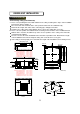
CONTENTS 1. PRECAUTIONS................................................................................................1 2. INSTALLATION INFORMATION......................................................................2 3. ATTACHED FITTINGS.....................................................................................3 4. INSTALLATION PLACE...................................................................................4 5. INDOOR UNIT INSTALLATION....................................................
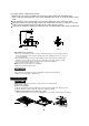
PRECAUTIONS SAFETY CONSIDERATIONS Installation and servicing of air conditioning equipment can be hazardous due to system pressure and electric components. Only trained and qualified service personnel should install, repair or service air conditioning equipment. All other operations should be performed by trained service personnel. When working on air conditioning equipment, observe precautions in the literature, tags and labels attached to the unit and other safety precautions that may apply.
NOTE Remark per EMC Directive 89/336/EEC For to prevent flicker impressions during the start of the compressor (technical process) ,following installation conditions do apply. 1. The power connection for the air conditioner has to be done at the main power distribution. The distribution has to be of a low impedance, normally the required impedance reaches at a 32 A fusing point. 2. No other equipment has to be connected with this power line. 3.
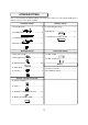
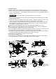
ATTACHED FITTINGS Please check whether the following fittings are of full scope. If there are some attached fittings free from use, please restore them carefully. Installation Fittings Tubing & Fittings 1. Expansible hook..........................................4? 5. Connecting pipe group...............................1 6. Binding tape................................................6 2. Installation hook..........................................4 7. Soundproof / insulation sheath...................
INSTALLATION PLACE CAUTIONS Location in the following places may cause malfunction of the machine.(If unavoidable, please consult your local dealer) a. There is petrolatum existing. b. There is salty air surrounding (near the coast). c. There is caustic gas (the sulfide, for example) existing in the air (near a hot spring). d. The Volt vibrates violently (in the factories). e. In buses or cabinets. f. In kitchen where it is full of oil gas. g. There is strong electromagnetic wave existing. h.
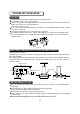
INDOOR UNIT INSTALLATION 1. Install the main body A. The existing ceiling (to be horizontal) a. Please cut a quadrangular hole of 880×880mm in the ceiling according to the shape of the installation paper board. (Refer to Chart3, 4) The center of the hole should be at the same position of that of the air conditioner body. Determine the lengths and outlets of the connecting pipe, drainpipe and cables. To balance the ceiling and to avoid vibration, please enforce the ceiling when necessary. b.
The length could be calculated from Chart5 Length=H-181+L (in general, L=100mm and is half of the whole length of the installation hook) c. Please adjust the hexangular nuts on the four installation hooks evenly, to ensure the balance of the body. If the drainpipe is awry, leakage will be caused by the malfunction of the water-level switch. Adjust the position to ensure the gaps between the body and the four sides of ceiling are even.
(3) Install the panel a. Align the swing motor on the panel to the tubing joints of the body properly. ( Refer to chart 11) b. Fix hooks of the panel at swing motor and its opposite sides to the hooks of corresponding water receiver. ( Refer to chart 11①) Then hang the other two panel hooks onto corresponding hangers of the body. ( Refer to chart 11②) CAUTIONS Do not coil the wiring of the swing motor into the seal sponge. c.
OUTDOOR UNIT INSTALLATION CAUTIONS Keep this unit away from direct radiation of the sun or other heaters. If unavoidable, please cover it with a shelter. In places near coast or with a high attitude where the wind is violent, please install the outdoor unit against the wall to ensure normal performance. Use a baffle when necessary. In the case of extremely strong wind, please prevent the air from flowing backwards into the outdoor unit.
INSTALL THE CONNECTING PIPE CAUTIONS Check whether the height drop between the indoor unit and outdoor unit, the length of refrigerant pipe, and the number of the bends meet the following requirements: The max height drop......................................................................................................................20m (If the height drop is more than 10m, you had better put the outdoor unit over above the indoor unit.) The length of refrigerant pipe....................................
Use the market brass pipe Be sure to use the same insulating materials when you buy the brass pipe (more than 9mm thick). 2. Locate The Pipes Drill a hole in the wall (suitable just for the size of the wall conduit, 53, 71 series diameter is Ф90mm, and 120,105,140 series diameter is Ф105 in general), then set on the fittings such as the wall conduit and its cover. Bind the connecting pipe and the cables together tightly with binding tapes. Do not let air in, which will cause water leakage by condensation.
Expel the air with a vacuum pump ( Refer to Chart 25) (please refer to its manual for the way of using manifold value) 1. Loosen and remove the maintenance nuts of stop values A and B, and connect the charge hose of the manifold value with the maintenance terminator of stop value A. (Be sure that stop values A and B are both closed) 2. Connect the joint of the charge hose with the vacuum pump. 3. Open the Lo-lever of the manifold value completely. 4. Turn on the vacuum pump.
INSULATION Be sure to with insulating materials cover all the exposed parts of the flare pipe joints and refrigerant pipe on the liquid-side and the gas-side. Ensure that there is no gap between them. Incomplete insulation may cause water condensation. CONNECT THE DRAIN PIPE 1. Install the drainpipe of the indoor unit You can use a polyethylene tube as the drainpipe (out-dia.37-39mm, in-dia.32mm). It could be bought at local market or from your dealer.
2. Drainage test Check whether the drainpipe is unhindered New built house should have this test done before paving the ceiling. 1) Remove the test cover, and stow water of about 2000ml to the water receiver through the stow tube. ( Refer to Chart 30) Pump joint Test cover Test mouth Body Stow tube Water-receiver Drain plug Chart 30 2) Turn on the power, and operate the air conditioner under the "COOLING" mode. Listen to the sound of the drain pump.
Installation of Flange and duct Fres h air is intaken by indoor fan motor s or duct able fan motor devices on field . The positions o f fr esh air intakecan be changed acco rding to the insta llation of ductable f an motor. 96 80 57 4-φ 6 Hole Note: 1. The device can be installed in ceiling cassette type indoor units (several-direction flow). 2. When installing the device, duct is needed on field and the rated diameter is 75mm.
Stick insulation material 4 at indoor hole Installa tion Typ e 2 Installa tion Type 1 Put t he in sulati on ma teria l 4 on the in terfa ce of th e hole as s hown in Fig ure 4 , then stick on th e ins ide an d sur face of the boar d. Th e inter face of the hole can n ot ha ve ga p.
WIRING CAUTION 1. The air conditioner should use separate power supply with rated voltage. 2. The external power supply to the air conditioner should have ground wiring, which is linked to the ground wiring of the indoor and outdoor unit. 3. The wiring work should be done by qualified persons according to circuit drawing. 4. A disconnection device having an air gap contact separation in all active conductors should incorporated in the fixed wiring according to the National wiring regulation. 5.
18000Btu/h (For R407C and R410A, Cooling only ) TYPE(Btu/h) PHASE POWER 1-PHASE FREQUENCY AND VOLT 24000Btu/h 30000-36000Btu/h (For R407C and R410A, Cooling only ) (For R407C and R410A, Cooling only ) 1-PHASE 1-PHASE 220-240V~, 50Hz 220-240V~, 50Hz 220-240V~, 50Hz ( A) 30/25 40/25 40/25 INDOOR UNIT POWER WIRING(mm ) 3x2.0 3x2.5 3x3.5 2.0 2.
2. Remove the protection board. Disassemble the bolts from the maintenance board, and pull it in the direction of the arrow to remove the protection board. Notice: Do not scratch the surface during operation. Terminator Protection board Chart 32 ATTENTION: Chart 32 is based on the standard model, which may look a little different from your own outdoor unit.
XT2 XT1 T3 E 18000Btu/h (1 P HASE) Air Condition Link-Circuit (For R407C and R410A,Heating&Cooling ) Chart 34 L N 1 2 3 L1 N1 L N 24000Btu/h (1 PHASE) Air Condition Link-Circuit (For R407C and R410A,Heating&Cooling ) Chart 35 19
1 2 3 5 4 C 1 6 C B A N 24000-30000Btu/h (3 PHASE) (For R407C ,Heating&Cooling ) 240 00Btu /h(3 PHASE) (For R410A ,Heating&Cooling ) Air Condition Link-Circuit Chart 36 1 2 3 4 5 6 L N 30000-36000Btu/h (1 PHASE ) (For R407C and R410A,Heating&Cooling ) Air Condition Link-Circuit Chart 37 20
1 2 3 4 5 6 C1 C B A N 36000-48000Btu/h (3 PHASE ) (For R407C ,Heating&Cooling ) 30000-48000Btu/h (3 PHASE ) (For R410A,Heating&Cooling ) Air Condition Link-Circuit Chart 38 XT1 18000Btu/h (1 PHASE) (For R407C and R410A,Cooling only) Air Condition Link-Circuit Chart 39 21
L N 1 2 3 L1 N1 L N 24000Btu/h (1 PHA SE) Air Condition Link-Circuit (For R407C and R410A,Cooling only) Chart 40 1 2 3 4 5 C 1 6 C B A N 24000-30000Btu/h (3 PHASE) (For R407C ,Cooling only) 24000Btu/h (3 PHASE ) Air Condition Link-Circuit (For R410A ,Cooling only) Chart 41 22
1 2 3 4 5 6 L N 30000-36000Btu/h (1 PHASE) Air Condition Link-Circuit (For R407C and R410A,Cooling only) Chart 42 1 2 3 4 5 6 C1 C B A N 36000-48000Btu/h (3 PHASE) (For R407C ,Cooling only) 30000-48000Btu/h (3 PHASE) (For R410A ,Cooling only) Air Condition Link-Circuit Chart 43 23
TEST OPERATION 1. The test operation must be carried out after the entire installation has been completed. 2. Please confirm the following points before the test operation: The indoor unit and outdoor unit are installed properly. Tubing and wiring are correctly completed. The refrigerant pipe system is leakage-checked. The drainage is unimpeded. The heating insulation works well. The ground wiring is connected correctly.
MDV04I-008bW