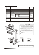
ROOM AIR CONDITIONER INSTALLATION MANUAL (Inverter Split Type) Please read this installation manual completely before installing the product. When the power cord is damaged, replacement work shall be performed by authorized personnel only. Installation work must be performed in accordance with the national wiring standards by authorized personnel only. Contact the authorised service technician for repair or maintenance of this unit.
CONTENTS SAFETY PRECAUTIONS...................................................................2 INSTALLATION OF INDOOR AND OUTDOOR UNITS.......................3 ELECTRICAL WORK ........................................................................9 AIR PURGING ..................................................................................11 TEST RUNNING...............................................................................
SAFETY PRECAUTIONS The following should be always observed for safety: Be sure to read the following WARNING before installing the air conditioner. Be sure to observe the cautions specified here as they include important items related to safety. After reading this instructions, be sure to keep it together with the owners manual in a handy place for future reference. ! WARNING Perform the installation securely referring to the installation instruction. Do not install it yourself.
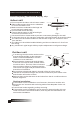
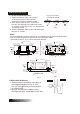
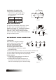
INSTALLATION OF INDOOR AND OUTDOOR UNITS Read completely, then follow step by step. More than 15cm Indoor unit Do not expose the indoor unit to heat or steam. More than 12cm More than 12cm Select a place where there are no obstacles in front or around the unit. Make sure that condensation drainage can 2.3m or more be conveniently routed away. Do not install near a doorway. Ensure that the space on the left and right Fig.1 of the unit is more than 12cm.
Items packed with the unit Number Q ty Name of Accessories 1 Installation Plate 1 2 Clip Anchor 8 3 Self-tapping Screw A ST3.9X25 4 Seal Drain Joint 8 1 5 Connecting pipe Assembly 6 1 Liquid side Gas side 6.35 9.53 ( 12.7 Parts you must purchase 12000Btu/h model) ( 12000Btu/h model) 7 Remote controller 1 8 Self-tapping Screw B ST2.9X10 2 9 Remote controller holder 1 Note: Except the above parts provided, the other parts needed during installation you must purchase.
INDOOR UNIT INSTALLATION 1. Fit the Installation Plate Correct orientation of Installation Plate 1. Fit the installation plate horizontally on structural parts of the wall with spaces around the installation plate. 2. If the wall is made of brick, concrete or the like, drill eight (8) 5mm diameter holes in the wall. Insert Clip anchor for appropriate mounting screws. 3. Fit the installation plate on the wall with eight (8) type “A” screws. Fig.
3. Connective Pipe and Drainage Installation Drainage 1. Run the drain hose sloping downward. Do not install the drain hose as illustrated below. Do not block water flow by a rise. Do not put the end of drain hose into water. Fig.6 2. When connecting extension drain hose, insulate the connecting part of extension drain hose with a shield pipe, do not let the drain hose slack. Connective pipe 1. For the left-hand and right-hand piping, remove the pipe cover from the side panel.
5. Piping and wrapping Bundle the tubing, connecting cable, and drain hose with tape securely, evenly as shown in Fig.10. Because the condensed water from rear of the indoor unit is gathered in ponding box and is piped out of room. Do not put anything else in the box. Indoor unit Connective cable Ponding box Pipe room Connective pipe Wrapping belt Drain hose Fig.10 CAUTION Connect the indoor unit first, then the outdoor unit. Do not allow the piping to let out from the back of the indoor unit.
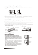
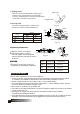
Model A(mm) 18000Btu/h 530 290 18000Btu/h 560 335 A Air inlet Air inlet B Settlement of outdoor unit Anchor the outdoor unit with a bolt and nut 10 or 8 tightly and horizontally on a concrete or rigid mount. B(mm) Air outlet Fig.12 Drain joint installation Fit the seal into the drain elbow, then insert the drain joint into the base pan hole of outdoor unit, rotate 90 to securely assemble them.
C: Putting nut on Remove flare nuts attached to indoor and outdoor unit, then put them on pipe/tube having completed burr removal.(not possible to put them on after flaring work) Flare nut Copper tube D: Flaring work Firmly hold copper pipe in a die in the dimension shown in the table below. Fig.16 "A" Bar Handle Bar Yoke Outer diam. (mm) 6.35 9.53 12.7 A(mm) Max. 1.3 1.6 1.8 Cone Min. 0.7 1.0 1.0 Copper pipe Clamp handle Red arrow mark Fig.
Power supply Model 18000Btu/h Input Rated Amp (Switch/Fuse) Power Cord Size 25A 1.5mm2 25A 2.5mm2 220-240V~ 50Hz 18000Btu/h NOTE: The supply voltage should be consistent with the rated voltage of the air conditioner. Connect the cable to the indoor unit 1. Indoor/Outdoor connection cable should be H07RN-F type. 2. Remove the panel and Screw, then remove the window cover. 3. Connect cables according to their marks to terminals. 4.
CAUTION CAUTION CAUTION CAUTION After the confirmation of the above conditions, prepare the wiring as follows: 1) Never fail to have an individual power circuit specifically for the air conditioner. As for the method of wiring, be guided by the circuit diagram posted on the inside of control cover. 2) The screw which fasten the wiring in the casing of electrical fittings are liable to come loose from vibrations to which the unit is subjected during the course of transportation.
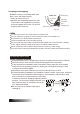
When relocate the unit to another place, perform evacuation using vacuum pump. Make sure the refrigerant added into the air conditioner is liquid form in any case. (Not applicable to the units with R22 refrigerant) Caution in handling the packed valve Open the valve stem until it hits against the stopper. Do not try to open it further. Securely tighten the valve stem cap with a spanner or the like. Valve stem cap tightening torque (See Tightening torque table in previous page ).
ELECTRICAL SAFETY AND GAS LEAK CHECK Electrical safety check Perform the electric safe check after completing installation: 1. Insulated resistance The insulated resistance must be more than 2M . 2. Grounding work After finishing grounding work, measure the grounding resistance by visual detection and grounding resistance tester. Make sure the grounding resistance is less than 4 . 3.
CS309-I 2200019589