
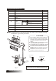
Installation Instructions

5
Installation Instruction
INDOOR UNIT INSTALLATION
1.
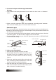
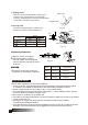
2. Drill a hole in the wall
Fig.4
Fig.5
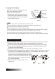
Note:
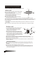
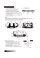
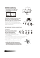
Fit the Installation Plate
1. Fit the installation plate horizontally
on structural parts of the wall with
spaces around the installation plate.
2. If the wall is made of brick, concrete or
the like, drill eight (8) 5mm diameter holes
in the wall. Insert Clip anchor for appropriate
mounting screws.
3. Fit the installation plate on the wall with eight
(8) type “A” screws.
Correct orientation
of Installation Plate
Fit the Installation Plate and drill holes in the wall according to the wall structure
and corresponding mounting points on the installation plate.
(Dimensions are in “mm” unless otherwise stated)
1. Determine hole positions according to
the diagram detailed in Fig.5. Drill
one (1) hole ( 65mm) slanting slightly
to outdoor side.
2. Always use wall hole conduit when
drilling metal grid, metal plate or the like.
Wall
Indoor
Outdoor
5-7mm
12000Btu/h model 18000Btu/h
Fig.6
270~370
878
659
133
40
40
270
27
6
55
55
39
Above 15cm from the ceiling
Outline of the Indoor Unit
Installation Plate
Above 12cm
from the wall
Above 12cm
from the wall
Rear-right Pipe
Hole 65
Rear-left Pipe
Hole 65
Above 15cm from the ceiling
Outline of the Indoor Unit Installation Plate
Above 12cm
from the wall
Rear-right Pipe
Hole 65
Rear-left Pipe
Hole 65
Above 12cm
from the wall
12000Btu/h model
70
750
45
250
70
-
--
--
--
-
--
--
--
-
--
--
-
-
-
--
-
--
--
--
-
--
--
--
-
--
--
-
-
-
--
18000Btu/h model
Indoor unit outline
120mm or more
to wall
120mm or more
to wall
Left refrigerant
pipe hole 65
Right refrigerant
pipe hole 65
Installation plate
293
920
150mm or more to ceiling
50
50