
Operation Manual
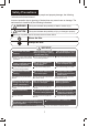


PARTS NAMES
4
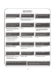
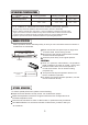
FUNCTION INDICATORS ON
INDOOR UNIT DISPLAY PANEL
AUTO indicator
This indicator illuminates when the air
conditioner is in AUTO operation.
TIMER indicator
This indicator illuminates when
TIMER is set ON/OFF.
PRE.-DEF. Indicator
(For Cooling & Heating models only)
This indicator illuminates when the air
conditioner starts defrosting
automatically or when the warm air control
feature is activated in heating operation.
The operation indicator lights flash rapidly
(five times per second.) when safety protection
features come into operation.
Note:
All the pictures in this manual are for explanation
purpose only. They may be slightly different from
the air conditioner you purchased(depend on model).
The actual shape shall prevail.
4
3
5
2
6
1
10
9
12
13
11
7
88
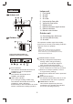
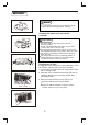
Indoor unit
Outdoor unit
1. Front panel
2. Air inlet
3. Air filter
4. Air outlet
5. Horizontal air flow grille
6. Vertical air flow louver
7. Display panel
8. Remote controller signal receiver
9. Remote controller
10. Manual control button
11. Connecting pipe, drain hose
12. Air inlet (side and rear)
13. Air outlet
Indoor unit
Outdoor unit
1
22
3
4
5
6
1
22
3
4
A) Usually it displays the temperature
settings. When change the setting
temperature, this indicator begins to
flash, and stops 20 seconds later.
B) It displays the room temperature when
the air conditioner is in FAN only operation.
C) When the unit stops operation, it return
to original factory settings.
D) Displays the malfunction code or protection
code.
OPERATION indicator
This indicator flashes after power is on and
illuminates when the unit is in operation.
FREQUENCY indicator
This indicator appears only when the
compressor is in operation and indicates
the current operating frequency.
TEMPERATURE indicator
5
6
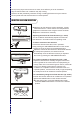
On/Off
Sleep
Fan
Swing
Air Direction
Timer On
Timer Off
Mode
Hr.
ON T
IMER
Hr.
Off T
IMER
SET TEMP
Auto