
Installation Instructions

1
2
3
4
5
6
7
1
1
1
8
8
1
Parts you
must
purchase
Note: Except the above parts provided, the other parts needed during
installation you must purchase.
Mounting screw B
ST2.9x10-C-H
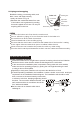
Remote controller
holder
This illustration is for explanation purposes only.
Copper lines must be insulated independently
4
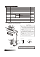
Installation Instruction
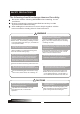
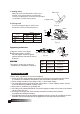
Items packed with the unit
6.35
9.53
12.7
8
2
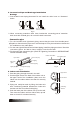
Loop the
connective
cable.
Self-tapping Screw B ST2.9X10
Fig.3
Remote controller
Installation Plate
Name of Accessories
Self-tapping Screw A ST3.9X25
Seal
Drain Joint
Connecting
pipe
Assembly
Liquid side
Clip Anchor
Number
Qty
Gas side
9
Remote controller holder
1
8
9
Remote Controller
7
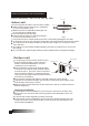
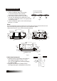
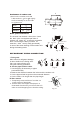
Ensure that the space around the left and
right of the indoor unit is more than 12cm.
The indoor unit should be installed allowing
a minimum clearance of 15cm from the
ceiling.
Use a stud finder to locate studs to prevent
unnecessary damage to the wall.
A minimum pipe run of 3 metres is required
to minimise vibration & excessive noise.
The indoor unit should be installed on the
wall at a height of 2.3 metres or more from
the floor .
At lease two of the Directions A, B and C
should be free from obstructions.
CAUTION
C
B
A
60cm
above
6
0c
m a
bo
ve
30cm
abov
e
200cm ab
ove
6
2
3
1
12cm above
12cm above
Air Filter
15cm above
Air Outlet
30cm
abov
e
( 12000Btu/h model)
( 12000Btu/h model)
On/Off
Sleep
Fan
Swing
Air Direction
Timer On
Timer Off
Mode
Hr.
ON TIMER
Hr.
Off TIMER
SET TEMP
Auto