Before using your air conditioner, please read this manual carefully and keep it for future reference. INVERTER ONE-TWO / ONE-THREE /ONE- FOUR SPLIT-TYPE ROOM AIR CONDITIONER Please read this installation manual completely before installing the product. If the power cord is damaged, replacement work shall be performed by authorised personnel only. Installation work must be performed in accordance with the national wiring Standards by authorised personnel only.
CONTENTS SAFETY PRECAUTIONS Warning ...........................................................................................................................................2 Caution ............................................................................................................................................2 INSTALLATION INSTRUCTIONS Selecting installation place...............................................................................................................3 Accessories .....
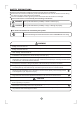
SAFETY PRECAUTIONS Read the follow SAFETY PRECAUTIONS carefully before installation. Electrical work must be installed by a licensed electrician. Be sure to use the correct rating and main circuit for the model to be installed. Incorrect installation due to ignoring of the instruction will cause harm or damage. The seriousness is classified by the following indications. WARNING This symbol indicates the possibility of death or serious injury.
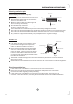
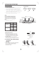
INSTALLATION INSTRUCTIONS Selecting installation place More than 15cm Read completely, then follow step by step. Indoor unit More than 12cm Do not expose the indoor unit to heat or steam. More than 12cm Select a place where there are no obstacles in front or around the unit. Make sure that condensation drainage can be conveniently routed away. More than 2.0m Do not install near a doorway. Fig.1 Ensure that the space on the left and right of the unit is more than 12cm.
INSTALLATION INSTRUCTIONS Tools needed for installation: Level gauge Screwdriver Electric drill,Hole core drill (φ65 mm) Flaring tool set Specified torque wrenches: 1.8kgf.m, 4.2kgf.m, 5.5kgf.m, 6.6kgf.m(different depending on model No.
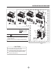
INSTALLATION INSTRUCTIONS Mor 2 e tha n 12 M or e th an cm More than 15cm 1 12 cm More 1 2 c m th a n 3 M or e th an 12 cm Ai r fil te r A ir fi lt er Ai r fil te r Ai r fil te r 4 5 Remote Remote controller Remote controller controller One-Two One-Three One-Four Mo 10c re tha m n Air out More than 60cm Remote controller 6 tha re Mo cm 30 n A CAUTIONS Mo This illustration is for explanation purposes only. The actual shape of your air condtioner may be slightly different.
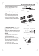
INSTALLATION INSTRUCTIONS Indoor unit installation Correct orientation of Installation Plate 1. Fit the Installation Plate 1. Fit the installation plate horizontally on structural parts of the wa ll with spaces around the installation plate. 2. If the wall is made of brick, concrete or the like, drill eight (8) 5mm diameter holes in the wall.Insert Clip anchor for appropriate mounting screws. 3. Fit the installation plate on the wall with eight (8) type A screws.
INSTALLATION INSTRUCTIONS 2. When connecting extension drain hose, insulate the connecting part of extension drain hose with a shield pipe, do not let the drain hose slack. Connective pipe installation Fig.8 1. For the left-hand and right-hand piping, remove the pipe cover from the side panel. 2. For the rear-right-hand and rear-left-hand piping, install the piping as shown in Fig.9. Bend the connective pipe to be laid at 43mm height or less from the wall. 3. Fix the end of the connective pipe.
INSTALLATION INSTRUCTIONS 4. Indoor unit installation 1. Pass the piping through the hole in the wall. 2. Put the upper claw at the back of the indoor unit on the upper hook of the installation plate, move the indoor unit from side to side to see that it is securely hooked (see Fig.12). 3. Piping can easily be made by lifting the indoor unit with a cushioning material between the indoor unit and the wall. Get it out after finish piping. 4.
INSTALLATION INSTRUCTIONS Outdoor unit installation Outdoor installation precaution Install the outdoor unit on a rigid base to prevent increasing noise level and vibration. Determine the air outlet direction where the discharged air is not blocked. In the case that the installation place is exposed to strong wind such as a seaside, make sure the fan operating properly by putting the unit lengthwise along the wall or using a dust or shield plates.
REFRIGERANT PIPE CONNECTION Drain joint installation Fit the seal into the drain elbow, then insert the drain joint into the base pan hole of outdoor unit, 。 rotate 90 to securely assemble them. Connecting the drain joint with an extension drain hose (Locally purchased), in case of the water draining off the outdoor unit during the heating mode. Base pan hole of outdoor unit Drain joint Seal Seal Drain pipe Fig.15 Refrigerant pipe connection 1.
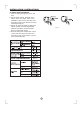
ELECTRICAL WORK D: Flaring work Firmly hold copper pipe in a die in the dimension shown in the table below. Outer diam. (mm) 6.35 9.53 12.7 "A" Bar Handle Bar Yoke A(mm) Max. 1.3 1.6 1.8 Cone Min. 0.7 1.0 1.0 Copper pipe Clamp handle Red arrow mark Fig.19 Tightening Connection Align the center of the pipes. Sufficiently tighten the flare nut with fingers, and then tighten it with a spanner and torque wrench as shown in Fig.20 & 21. Outer diam. Flare nut Pipings Fig.
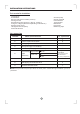
ELECTRICAL WORK Wiring connection Minimum norminal cross-sectional area of conductors: NOTE: Before performing any electrical work, turn off the main power to the system. Rated current of appliance Nominal cross-sectional area (mm 2) (A) CAUTIONS 0.75 >3 and <6 Do not touch the capacitor even if you have disconnected the power for there is still high voltage power on it, or electric shock hazard may occur.
ELECTRICAL WORK NOTE: For some models, the indoor unit is especially designed to used as either MULTI models or MONO models. If your air conditioner is not set to the MULTI position, see the following INDOOR WIRING DIAGRAM to modify the indoor unit from MONO model to MULTI model. (Fig.25 & 26) 1. Carefully remove the front panel and frame, then remove the Electricall control cover by loosen the screw. 2. Remove the POWER SUPPLY cord of MONO model(Fig.25). 3.
AIR PURGING CAUTION CAUTION CAUTION CAUTION After the confirmation of the above conditions, prepare the wiring as follows: 1) Never fail to have an individual power circuit specifically for the air conditioner. As for the method of wiring, be guided by the circuit diagram posted on the inside of control cover. 2) The screw which fasten the wiring in the casing of electrical fittings are liable to come loose from vibrations to which the unit is subjected during the course of transportation.
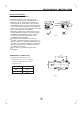
AIR PURGING When relocate the unit to another place, perform evacuation using vacuum pump. Make sure the refrigerant added into the air conditioner is liquid form in any case. (Not applicable to the units adopt freon R22 ) Refrigerant Outdoor unit Indoor unit A Gas side C Liquid side D B Caution in handling the packed valve Open the valve stem until it hits against the stopper. Do not try to open it further. Securely tighten the valve stem cap with a spanner or the like.
AIR PURGING Safety and leakage check ● Electrical safety check Perform the electric safe check after completing installation: 1. Insulated resistance The insulated resistance must be more than 2MΩ. 2. Grounding work After finishing grounding work, measure the grounding resistance by visual detection and grounding resistance tester. Make sure the grounding resistance is less than 4Ω. 3.
TEST RUNNING Test running Perform test operation after completing gas leak check at the flare nut connections and electrical safety check. Check that all tubing and wiring have been properly connected. Check that the gas and liquid side service valves are fully open. 1. Connect the power, press the ON/OFF button on the remote controller to turn the unit on. 2. Use the MODE button to select COOL, HEAT, AUTO and FAN to check if all the functions works well. 3.
CS464-I 202000191053