
Installation Instructions


NOTE:
For some models, the indoor unit is especially designed to used as either MULTI models
or MONO models. If your air conditioner is not set to the MULTI position, see the following
INDOOR WIRING DIAGRAM to modify the indoor unit from MONO model to MULTI model.
(Fig.25 & 26)
1. Carefully remove the front panel and frame, then remove the Electricall control cover
by loosen the screw.
2. Remove the POWER SUPPLY cord of MONO model(Fig.25).
3. Unplug the then connect it
with
“L” RED wire connected with “4” on pinboard of RY1,
“3” on pinboard of Ry1.
4. Reinstall the Electrical Control cover and screw, rip off the white paper above the
Slide Switch and move it to the MULTI position(see Fig. 25).
5. Reinstall the front panel and frame.
6. Now the indoor unit can be used as MULTI models(Fig.26). Because the control
system is changed, the AUTO CLEAN function is unavailable for MULTI models.
INDOOR FAN MOTOR
LOUVER MOTOR
N
CN1
CN3
CN6
CN7
CN8
CN2
CN17
CN9
5
7
L
N
S
L
Y/G
BLACK
RED
S
L
N
WHITE
RED
CN14
CN11
OUTDOOR UNIT
INDOOR PCB
2
4
S
YELLOW
TRANSFORMER
JX1
INDOOR WIRING DIAGRAMINDOOR WIRING DIAGRAM
ROOM TEMP. SENSOR
PIPE TEMP. SENSOR
CN4
AUTO RESTART
CN15
IONIZER
SWITCH BOARD
DISPLAY BOARD
5
5
CN12
CN13
3
3
2
2
3
3
RY1
3
4
CN5
2
PLUMB STEP MOTOR
DOOR STEP MOTOR
2205209008
INDOOR FAN MOTOR
LOUVER MOTOR
N
CN1
CN3
CN6
CN7
CN8
CN2
CN17
CN9
5
7
BROWN
BLUE
L
N
S
L
Y/G
BLACK
RED
S
L
N
WHITE
RED
CN14
CN11
OUTDOOR UNIT
INDOOR PCB
POWER SUPPLY
2
4
S
YELLOW
TRANSFORMER
JX1
Y/G
INDOOR WIRING DIAGRAMINDOOR WIRING DIAGRAM
ROOM TEMP. SENSOR
PIPE TEMP. SENSOR
CN4
AUTO RESTART
CN15
IONIZER
SWITCH BOARD
DISPLAY BOARD
5
5
CN12
CN13
3
3
2
2
3
3
RY1
3
4
CN5
2
PLUMB STEP MOTOR
DOOR STEP MOTOR
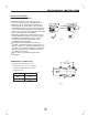
MONO MODELS
MULTI MODELS
MONO
MONO
MULTI
Rip off the
white paper
MONO
MONO
MULTI
Fig.25
Fig.26
ELECTRICAL WORK
13