
Installation Instructions

6
INSTALLATION INSTRUCTIONS
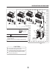
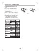
Fig.4
Correct orientation
of Installation Plate
Wall
Indoor
Outdoor
5-7mm
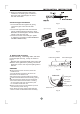
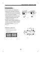
Fig.6
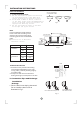
Fig.5
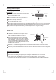
Indoor unit installation
2. Drill a hole in the wall
Note:
1. Fit the Installation Plate
1. Fit the installation plate horizontally
on structural parts of the wall with
spaces around the installation plate.
2. If the wall is made of brick, concrete
or the like, drill eight (8) 5mm diameter
holes in the wall.Insert Clip anchor for
appropriate mounting screws.
3. Fit the installation plate on the wall
with eight (8) type A screws.
Fit the Installation Plate and drill
holes in the wall according to the
wall structure and corresponding
mounting points on the installation
plate.
(Dimensions are in mm unless
otherwise stated)
1. Determine hole positions according
to the diagramdetailed in Fig.5. Drill
one (1) hole ( 65mm) slanting slightly
to outdoor side.
2. Always use wall hole conduit when
drilling metal grid, metal plate or the like.
φ
3. Connective Pipe and Drainage
Installation
1. Run the drain hose sloping downward.
Do not install the drain hose as
illustrated in Fig.7.
Drainage
Fig.7
Do not block water flow by a rise.
Do not put the end of
drain hose into water.
A
40
B
Right rear side
refrigerant
pipe hole 65φ
Installation plate
Indoor unit outline
Left rear side
refrigerant
pipe hole 65φ
150mm or more to ceiling
120mm or
more to wall
120mm or
more to wall
90
40
45
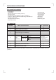
Model
A(mm)
710
B(mm)
250
<12000Btu/h
790
265
815
280
>12000Btu/h
780
270
780
270
750
250