
Operation Manual
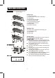
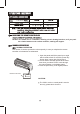
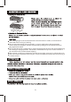

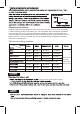
Table Of Contents

PARTS NAMES AND FUNCTIONS
Indoor unit
Outdoor unit
1. Front panel frame
2. Air filter. Antil- formol filter, HEPA filter
3 Front panel
4. Horizontal air flow grille
5. Vertical air flow louver
6. Room temperature sensor
7. Infrared signal receiver
8. Display lamp
9. Remote Controller
10. Drain hose, refrigerant connecting pipe
11. Connective cable
12. Stop valve
13. Fan hood
Display panel:
The operation lamp flashes once per second
when connecting power supply.
The operation lamp on the first operated unit
flashes two times per second, the lamp on the
second operated unit will be lit all the time.
The operation lamp will be off when the air
conditioner switch off.
The timer lamp will be lit when on/off time has
been set.
The DEF lamp will be lit while defrosting and
cooling air controlling.
The DEF lamp will be off while the indoor fan
operating(High,MED,Low,Slight)
The TIMER lamp and DEF lamp flash 5 times
per second while the modes conflicting.
The OPERATION lamp and DEF lamp flash 5
times per second while high cooling.
Indoor unit
Air outlet
2
1010
Air outlet
Air inlet
Air outlet
Air inlet
Air inlet
This chart takes wall-mounted
type as example.